Flexible fastening device for industrial use

a flexible and industrial technology, applied in the direction of threaded fasteners, screws, osteosynthesis devices, etc., can solve the problems of inability to use rigid devices, inability to drill another bore, and inability to bend rigid devices, etc., to achieve the effect of increasing the flexibility of the component, increasing the width, and limited flexibility

Active Publication Date: 2016-11-01
FLEX TECH
View PDF30 Cites 43 Cited by
  • Summary
  • Abstract
  • Description
  • Claims
  • Application Information

AI Technical Summary

Benefits of technology

[0019]A plurality of slots can be employed thereby increasing the flexibility of the component, relative to a shaft having a single slot of identical pattern. The serpentine path forms a plurality of teeth and complimentary recesses on opposite sides of the slot. The slot has sufficient width to form an unbound joint permitting limited movement in any direction between the teeth and the recesses, thereby providing limited flexibility in all directions upon application of tensile, compressive, and / or torsion forces to said component. In a similar manner the slot can have increased width in one direction compared to another direction thus providing increased flexibility in one direction.
[0020]The flexible segment can have different degrees of flexibility along the length of said shaft. The varied flexibility can be achieved by having the pitch of the helical slot vary along the length of the shaft. The varied flexibility corresponds to the variation in the pitch of the helical slot. The helical path can have a helix angle in the range of about 10 degrees to about 45 degrees, and the helix angle can be varied along the length of the shaft to produce correspondingly varied flexibility. Alternatively, the width of the helical slot can vary along the length of the shaft to provide the varied flexibility. The rigidity of the flexible shaft can be achieved through the design of the slot pattern, thereby enabling the use of thinner walls than would otherwise be require to produce equivalent rigidity. In a preferred embodiment, the ratio of the amplitude of the serpentine path to the pitch of the slot is in the range from greater than 0.1 to about 0.8.

Problems solved by technology

The larger trailing threads then engage the larger bore in the near bone fragment As a result of this arrangement, any stripping of the threads cut into the bones during installation of the screw occurs in the remote bone, causing the necessity of drilling another bore.
When the channel the device is to be inserted into is curved or misaligned, a straight, rigid device cannot be used.
In the case of a bone screw, unless the screw is initially inserted precisely along the center axis of the curved bone after reducing the fracture, the screw will cause the bone to rotate to align itself with the screw thus causing the fracture to open.
Another disadvantage of the prior art screws is that they generally follow the straight path and exit out of the side of the bone or enter the cortex of the bone, thus further weakening the bone.

Method used


Image

  • Flexible fastening device for industrial use
  • Flexible fastening device for industrial use
  • Flexible fastening device for industrial use

Examples


Embodiment Construction

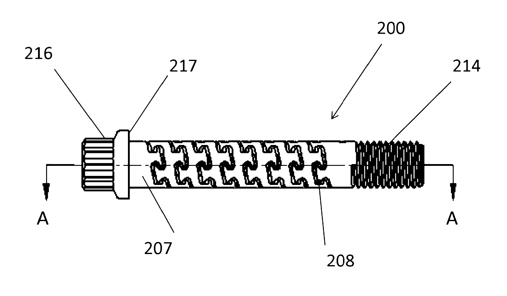
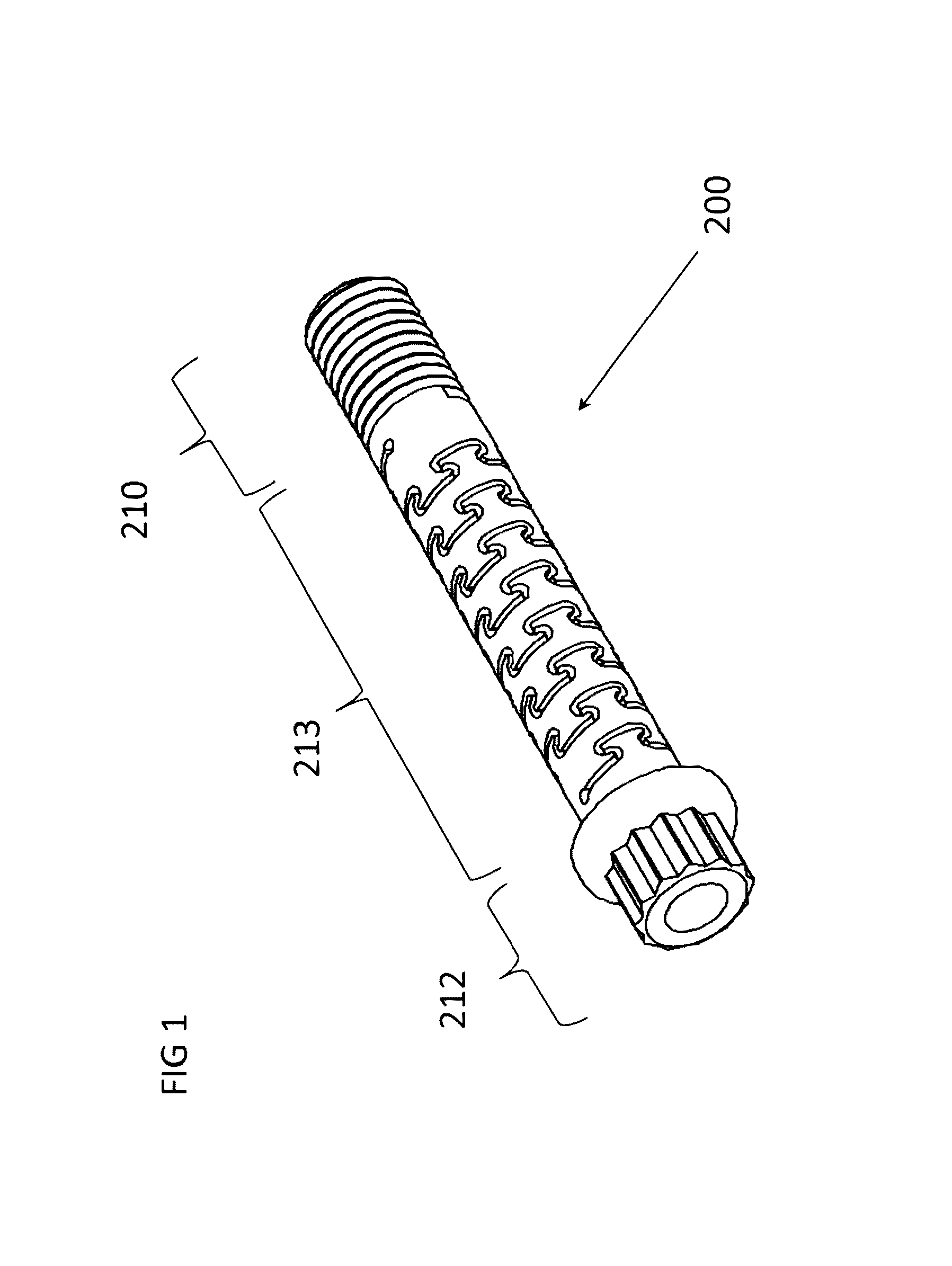
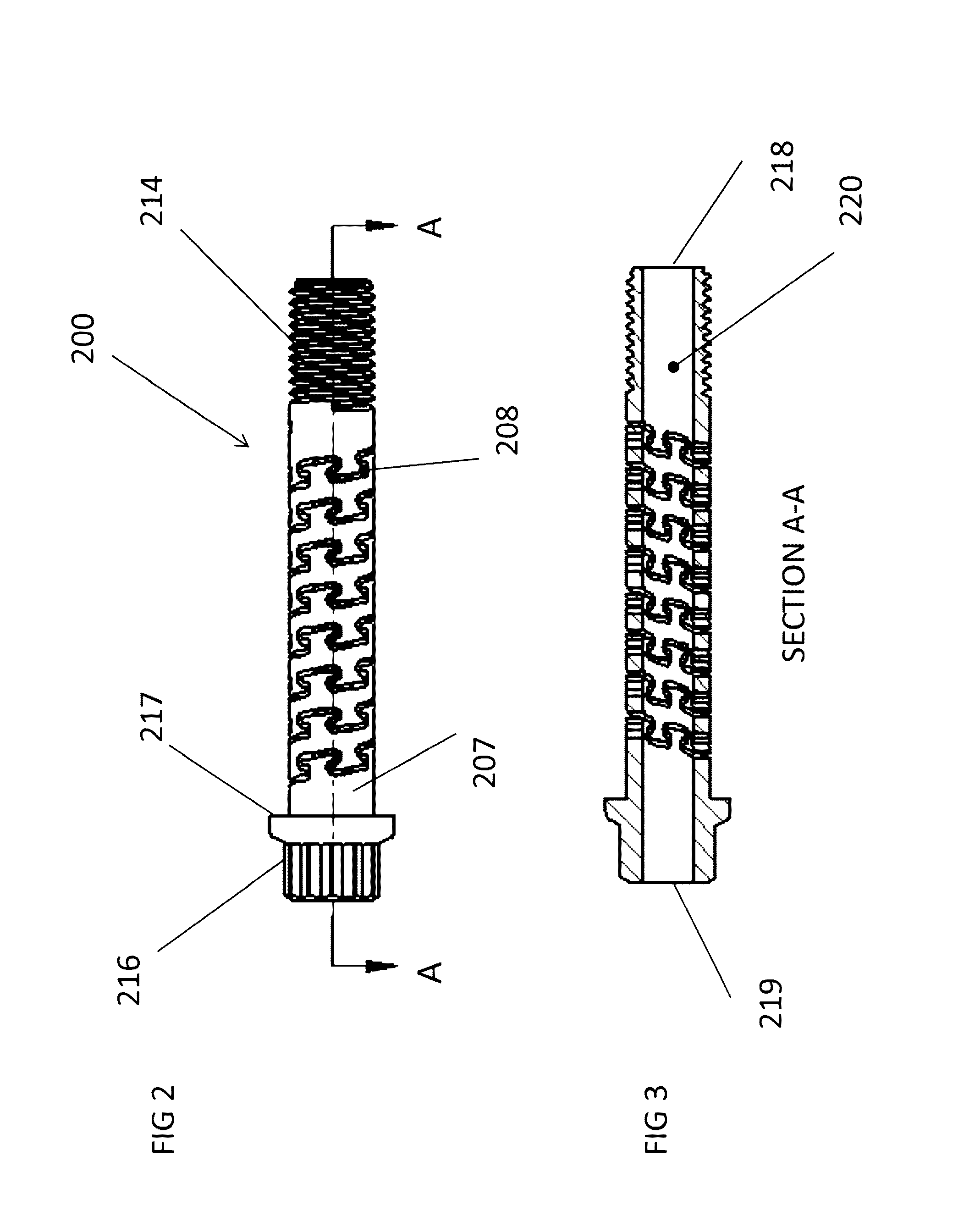
[0072]The flexible fastening device is composed of a rigid material with a body having a diameter, a length, and multiple defined segments, at least one of which has at least one helical slot to form a flexible segment with exterior threads on at least one of the segments. The leading segment is typically tapered in the case of a screw to provide for forward penetration into the material and is designed to cut a helical groove in a softer material as the screw is inserted. The leading segment may also have a blunt end, as in the case of a bolt, designed to mate with a complementary thread, known as an internal thread, often in the form of a nut or an object that has the internal thread formed into it. The trailing or driving segment is typically has a head shape, which may be pan, dome, round, truss (mushroom), flat (countersunk) or oval shaped, and has a receiving area to receive a rotational force device. The receiving area can employ a wide variety of drive designs, each requirin...


PUM

PropertyMeasurementUnit
helical angleaaaaaaaaaa
angleaaaaaaaaaa
helix angleaaaaaaaaaa

Abstract

A flexible fastening device having multiple segments, one or more of which are flexible and one or more segments that also include threads. The flexibility is created through the use of at least one helical slot formed generally in the center segment of the element. Additional flexible segments also have at least one helical slot in either the same helical rotation and pattern or in an opposite rotation and/or different pattern. An elastomeric material can fill the hollow body, extend into the slots and/or encompass the exterior. The flexible fastening device can have a hollow body, including leading and trailing edge, or can have a partially hollow body.

Description

CROSS REFERENCE[0001]This application is continuation in part of U.S. Ser. No. 12 / 712,174 filed Feb. 24, 2010 which is a non-provisional of provisional application 61 / 155,146 filed on Feb. 24, 2009 both of which are incorporated herein as though recited in full.FIELD OF INVENTION[0002]This invention relates to a flexible fastening device which two components are held together.DESCRIPTION OF THE RELATED ART[0003]A screw, or bolt, is a type of fastener characterized by a helical ridge, known as an external thread or just thread, wrapped around a cylinder. Some threads are designed to mate with a complementary thread, known as an internal thread, often in the form of a nut or an object that has the internal thread formed into it. Other threads are designed to cut a helical groove in a softer material as the screw is inserted. The most common uses of bolts and screws are to hold objects together and to position objects. Threaded fasteners either have a tapered shank or a non-tapered sha...

Claims


Application Information

Patent Timeline
Patent Type & Authority Patents(United States)
IPC IPC(8): F16B35/04A61B17/72A61B17/86
CPCF16B35/041A61B17/7225A61B17/8625A61B17/7291A61B17/8605A61B17/864A61B17/866A61B17/869F16B5/0275F16B25/0015F16B25/0094F16B33/006
Inventor KRAUSE, WILLIAM R
Owner FLEX TECH
Why Eureka
Try Eureka