Multifunctional health-care chair
A health-care chair and multi-functional technology, applied in passive exercise equipment, physical therapy and other directions, to achieve the best cardiovascular and cerebrovascular effects, physical exercise health care, and garbage removal effects
- Summary
- Abstract
- Description
- Claims
- Application Information
AI Technical Summary
Problems solved by technology
Method used
Image
Examples
specific Embodiment approach 1
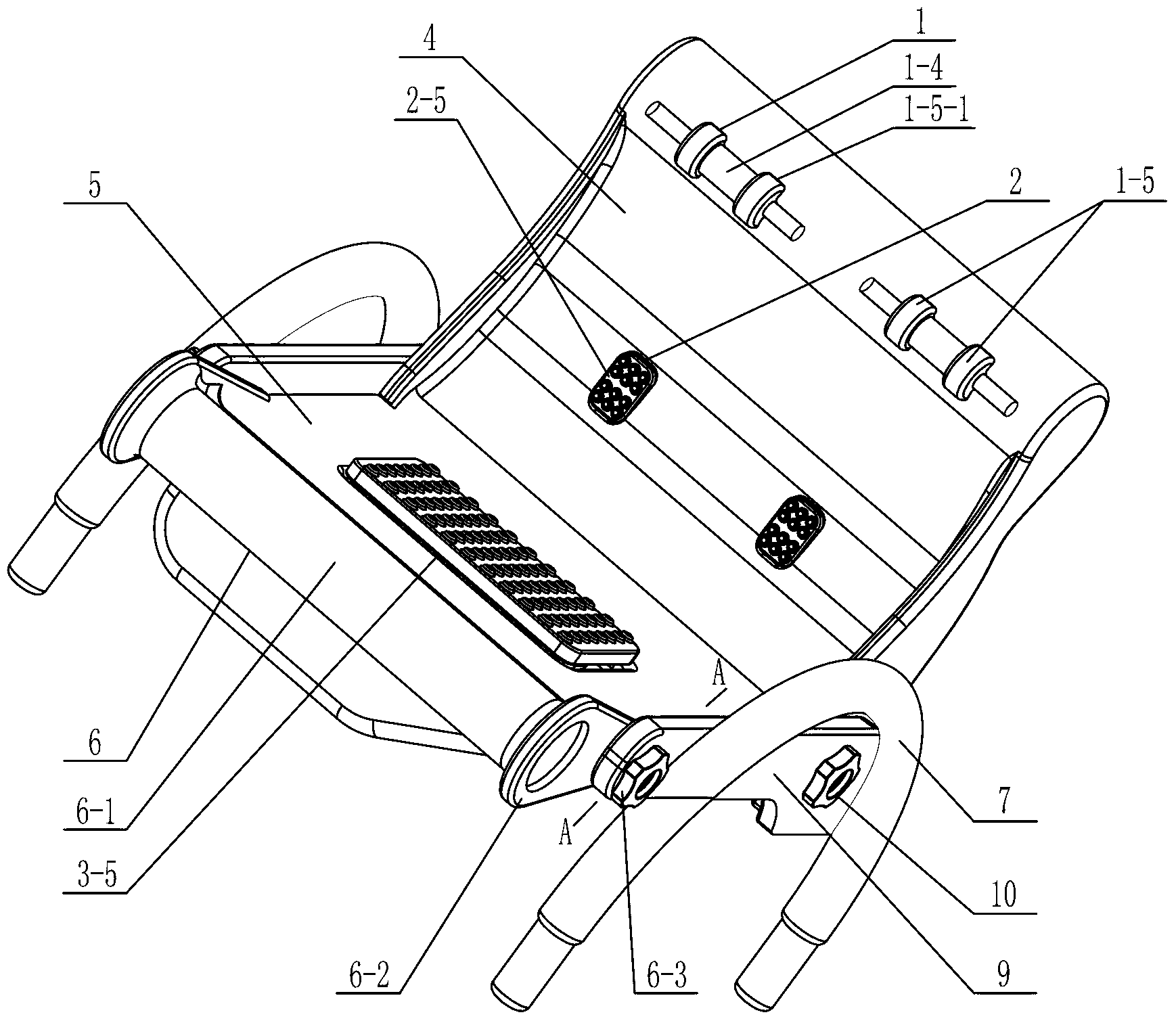
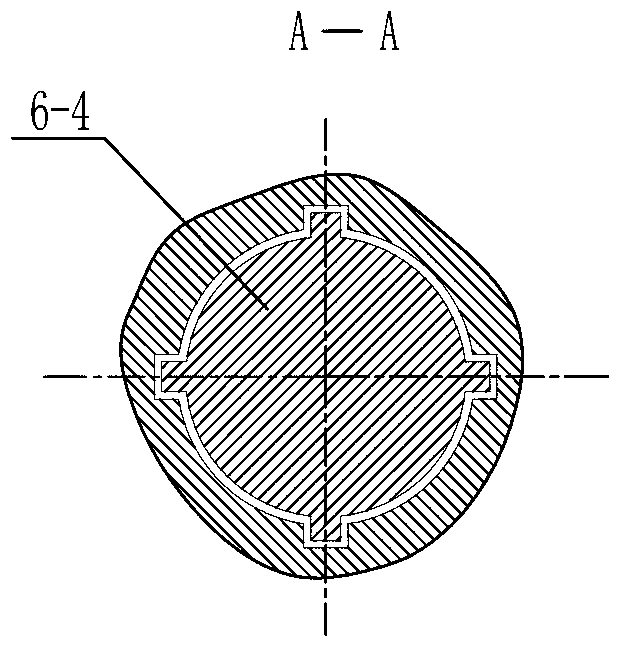
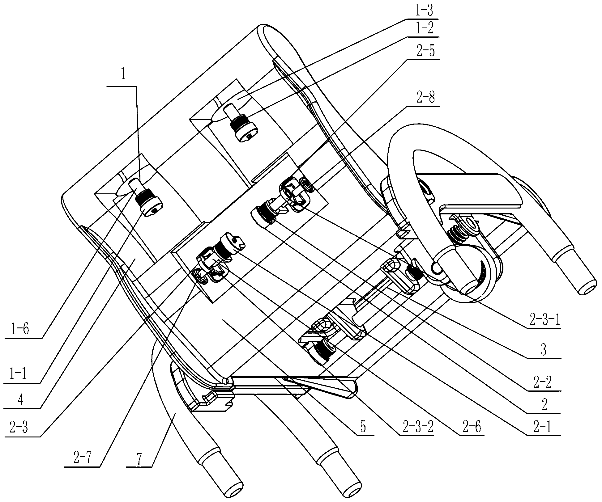
[0015] Specific implementation mode one: combine figure 1 , Figure 3 to Figure 8 Illustrate, the multifunctional health care chair of the present embodiment, it comprises chair back 4, seat seat 5, seat back angle adjustment limit mechanism 10, two seat side panels 9 and two armrests 7; Chair seat 5 is horizontally arranged, and chair seat The left and right sides of the seat 5 are respectively provided with a seat side plate 9, and an armrest 7 is respectively fixed on the outside of the seat side plate 9. The rear part of the chair back is connected, the angle between the initial position of the chair back 4 and the vertical direction is greater than 0°, and the angle between the end position of the chair back 4 and the vertical direction is less than 90°; the multifunctional health care chair also It includes two leg reciprocating motion devices 1, two thigh root lifting motion devices 2 and a hip jacking and horizontal reciprocating motion device 3; the two leg reciproca...
specific Embodiment approach 2
[0016] Specific implementation mode two: combination figure 1 , Figure 3 to Figure 5 Explain that the two leg reciprocating devices 1 in this embodiment all include a leg reciprocating motor 1-1 integrated with a reducer and a frequency converter, a leg reciprocating transmission device 1-3, and a horizontal reciprocating rod 1-4 , a leg reciprocating connection shaft 1-6, a leg reciprocating coupling 1-2 and two leg supporting devices 1-5; the leg reciprocating motor 1-1 integrated with a reducer and a frequency converter The output shaft of the leg is connected to one end of the leg reciprocating connection shaft 1-6 through the leg reciprocating coupling 1-2, and the other end of the leg reciprocating connecting shaft 1-6 is connected to the leg reciprocating transmission device 1-3 Fixed connection, leg reciprocating transmission device 1-3 is fixedly connected with horizontal reciprocating rod 1-4, and horizontal reciprocating rod 1-4 is arranged parallel to the width d...
specific Embodiment approach 3
[0018] Specific implementation mode three: combination figure 1 and image 3 Illustrate, the leg reciprocating transmission device 1-3 described in this embodiment is a worm gear transmission device or a rack and pinion transmission device, and the worm gear transmission device includes a leg reciprocating transmission worm wheel and a leg reciprocating transmission worm, and the gear teeth The bar transmission device includes the leg reciprocating transmission gear and the leg reciprocating transmission rack, the leg reciprocating transmission worm gear or the leg reciprocating transmission gear is fixedly set on the other end of the leg reciprocating connection shaft 1-6, the leg reciprocating transmission worm gear Engage with the leg reciprocating transmission worm, or the leg reciprocating transmission gear and the leg reciprocating transmission rack, the leg reciprocating transmission worm is a semi-cylindrical body, and the leg reciprocating transmission worm or the leg...
PUM
 Abstract
Description
Claims
Application Information
 - R&D
- Intellectual Property
- Life Sciences
- Materials
- Tech Scout
- Unparalleled Data Quality
- Higher Quality Content
- 60% Fewer Hallucinations
Browse by: Latest US Patents, China's latest patents, Technical Efficacy Thesaurus, Application Domain, Technology Topic, Popular Technical Reports.
© 2025 PatSnap. All rights reserved.Legal|Privacy policy|Modern Slavery Act Transparency Statement|Sitemap|About US| Contact US: help@patsnap.com


