
Time labelling associated with an equipment synchronisation system connected to a network

一种时间标签、接收设备的技术,应用在电气元件、脉冲调制电视信号传输、选择性内容分发等方向,能够解决有限制性、不能实现期望的时间标签功能等问题,达到缩短进步过程的效果

Inactive Publication Date: 2011-04-13
THOMSON LICENSING SA
View PDF4 Cites 5 Cited by
  • Summary
  • Abstract
  • Description
  • Claims
  • Application Information

AI Technical Summary

Problems solved by technology

[0012] The video synchronization device described in the international PCT application FR2007 / 050918 enables devices to be synchronized with the desired level of precision, but does not achieve the desired time-stamping function: the duration of the counting ramp (counting ramp) generated has a duration equal to 81 seconds duration of
Transmission of counted ramp samples enables precise knowledge of the current timestamp only for the duration of the ramp, but this is restrictive

Method used


Image

  • Time labelling associated with an equipment synchronisation system connected to a network
  • Time labelling associated with an equipment synchronisation system connected to a network
  • Time labelling associated with an equipment synchronisation system connected to a network

Examples


Embodiment Construction

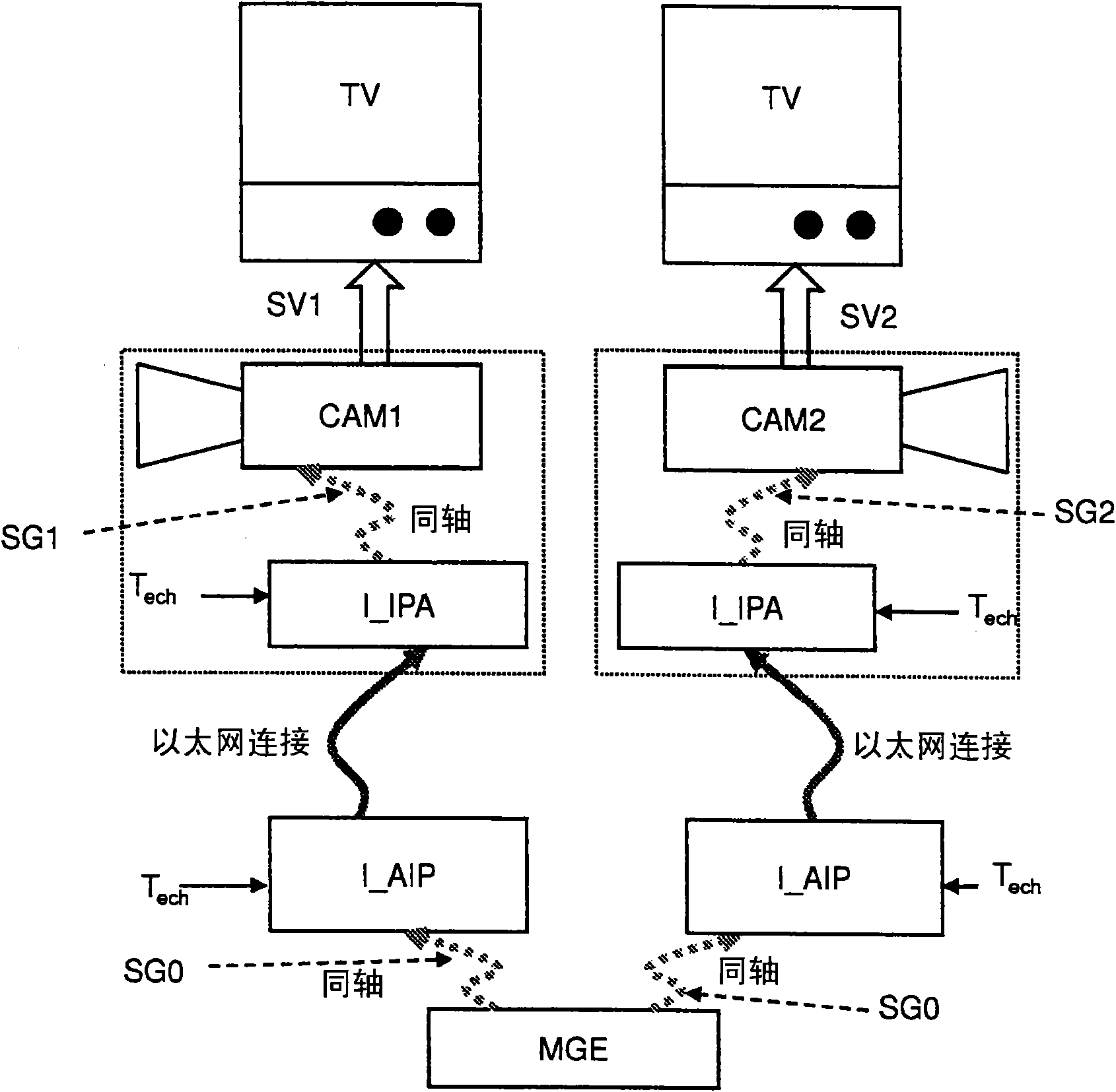
[0044] like figure 1 As shown, the current analog domain is interfaced with the IP / Ethernet network on the transmit side, and the IP / Ethernet network is interfaced with the analog domain on the receive side.

[0045] exist figure 1 , the sending side includes a "genlock master" MGE connected to the IP / analog interface I_AIP. The genlock master controller MGE sends a genlock signal SG0 to the interface I_AIP.

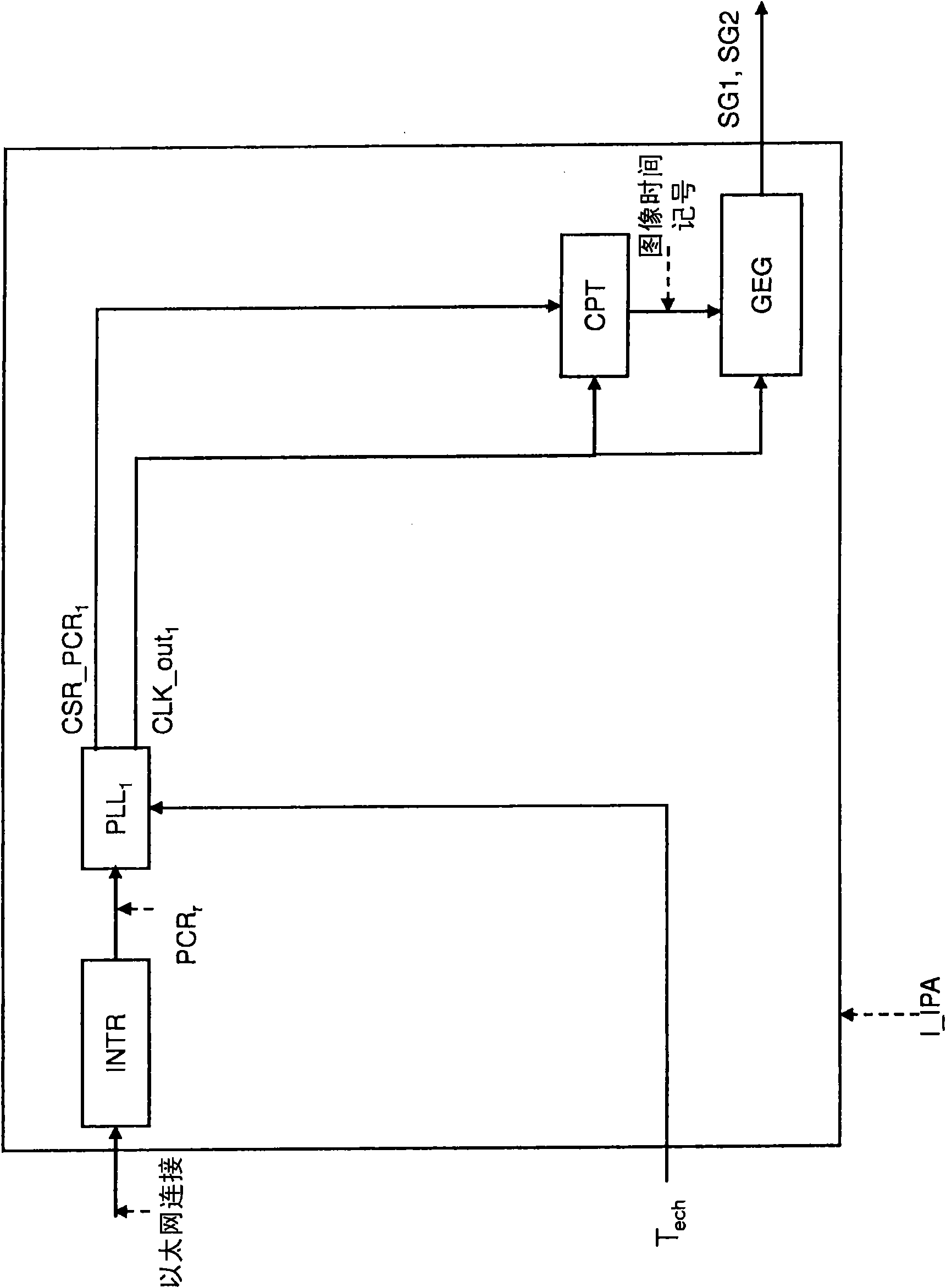
[0046] The receiving side consists of two cameras (CAM1, CAM2), which are respectively connected to the IP / analog interface I_IPA. The interface I_IPA eventually included in the camera itself is responsible for reconstructing the genlock signals SG1, SG2 for the cameras CAM1, CAM2. The cameras CAM1 and CAM2 generate video signals SV1 and SV2 respectively, and the video signals SV1 and SV2 are required to be ideally synchronized.

[0047] The transmitting and receiving sides are linked together by a packet-switched network, which is the source of the jitter that occur...


PUM


Abstract

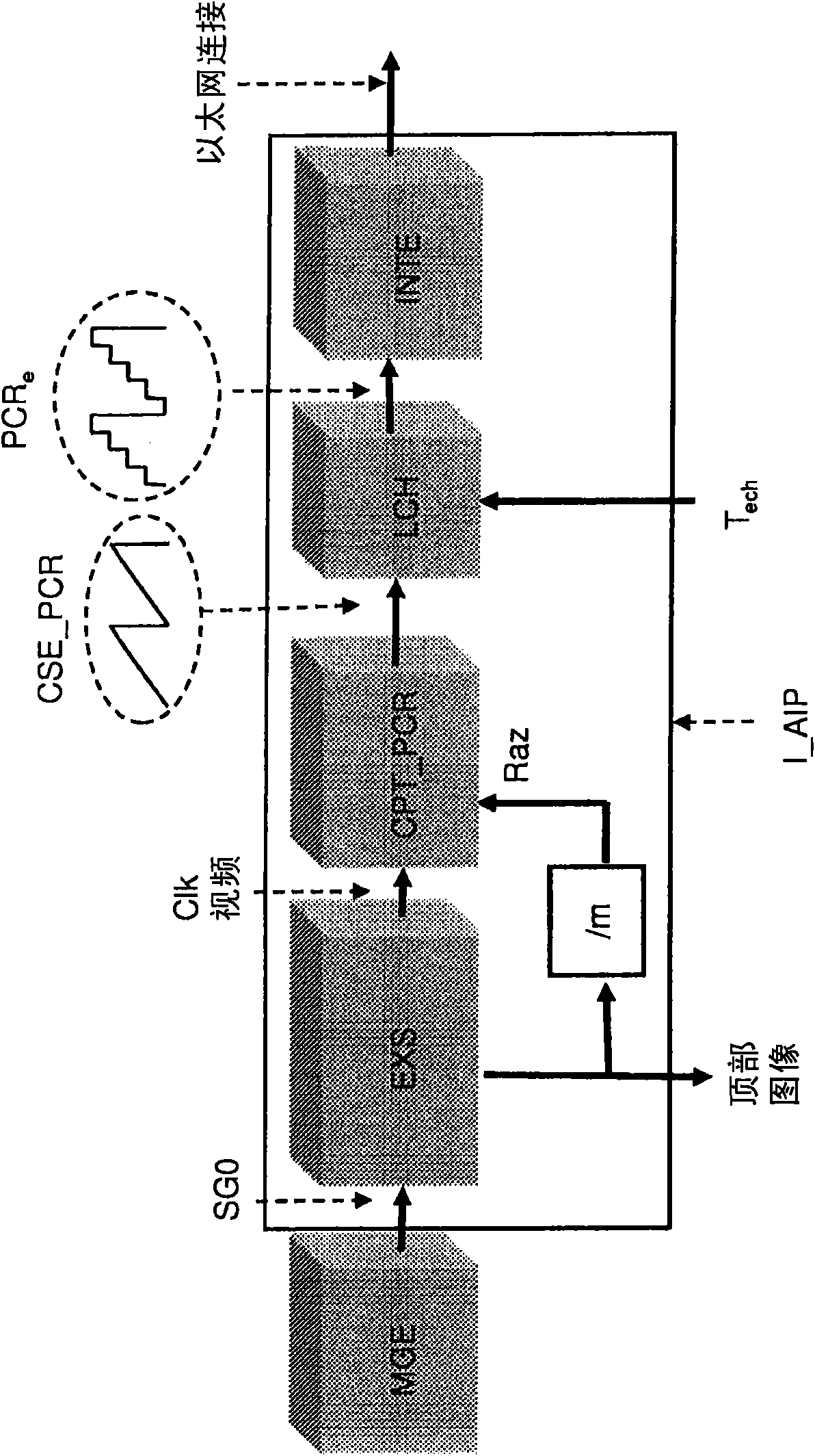
The present invention relates to the domain of video equipment. It concerns more specifically a transmission device able to transmit packets, said device comprising the means to extract image ticks from a synchronisation signal, the means to initialise an image counter from said image ticks, the means to initialise a CPT_ PCR counter every 'm' passage through zero of the image counter, CPT_PCR producing counting ramps CSE_PCR with a range M, the means to sample the counting ramps CSE_PCR every Tech period, where Tech is from a time base synchronised on all the stations of said network, and the means to transmit packets comprising a PCRe sample of the CSE_PCR counting ramp. According to the invention, it also comprises the means to insert in the packet: - an Num index identifying the CSE_PCR counting ramp from which the PCRe sample is realised, and - a time label Datejnit indicating a CSE_PCR counting ramp timestamp passage through a reference value PCR_REF comprised between 0 and M-1.

Description

technical field [0001] The present invention relates to the field of video equipment. [0002] The present invention more particularly relates to a device for synchronizing time stamps associated with devices connected via a packet-switched network, eg of the IP (Internet Protocol) type, whether wired (eg Ethernet (IEEE 802. 3)) Also wireless (eg IEEE802.16D-2004). Background technique [0003] The development of the ability of IP networks to transport all types of signals (data or video) has enabled the use of these networks as the "primary" architecture for video studios. The primary importance of this change is therefore to have a single infrastructure for data transfer. Whereas in the past several media were necessary to convey different signal types between devices, the multiplexing properties provided by the IP layer enabled to reduce the amount of media necessary for an IP network linking different devices. [0004] In the prior art, synchronization of video equipm...

Claims


Application Information

Patent Timeline
Patent Type & Authority Applications(China)
IPC IPC(8): H04N21/242H04N21/8547H04N7/24
CPCH04N21/4344H04N21/23608H04N21/4305H04N21/242
Inventor 蒂埃里·塔皮塞尔日·德弗朗斯皮埃雷克·茹埃
Owner THOMSON LICENSING SA
Learn More