Floating shaft lever sealing structure

A technology of sealing structure and floating shaft, which is applied in the direction of engine sealing, engine components, mechanical equipment, etc., can solve the problems of excessive eccentricity, large packing pressing force, misalignment of shaft axis and rotation center, etc., and achieve reduction The effect of valve operating torque, extended service life, and elimination of routine maintenance

Inactive Publication Date: 2011-04-20
SHANGHAI KARON VALVES MACHINERY +1
View PDF10 Cites 8 Cited by
  • Summary
  • Abstract
  • Description
  • Claims
  • Application Information

AI Technical Summary

Problems solved by technology

When the equipment is working, the shaft has a large vibration and deflection, which causes the axis of the shaft to not coincide with the rotation center, resulting in an excessive eccentricity between them, resulting in seal leakage and reduced service life.
At the same time, after the packing is worn out, the gap between the packing, the shaft and the inner wall of the stuffing box increases, and the packing has no ability to automatically compensate the pressing force. As the gap increases, the leakage gradually increases. Therefore, The gland bolts must be tightened frequently, and the maintenance workload for daily adjustment is heavy
The packing pressing force is high, which also leads to the increase of operating torque, which is not conducive to saving the energy consumption required by the driving device

Method used


Image

  • Floating shaft lever sealing structure
  • Floating shaft lever sealing structure
  • Floating shaft lever sealing structure

Examples


Embodiment Construction

[0012] The present invention will be further described below in conjunction with accompanying drawing.

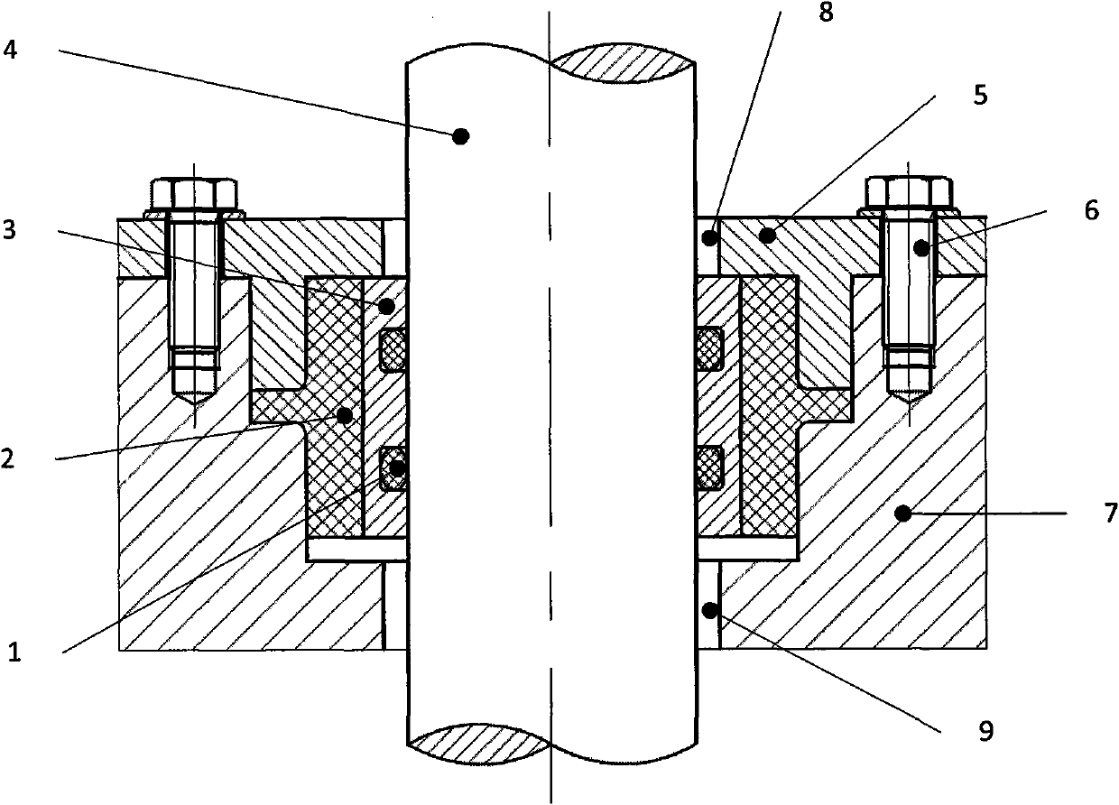
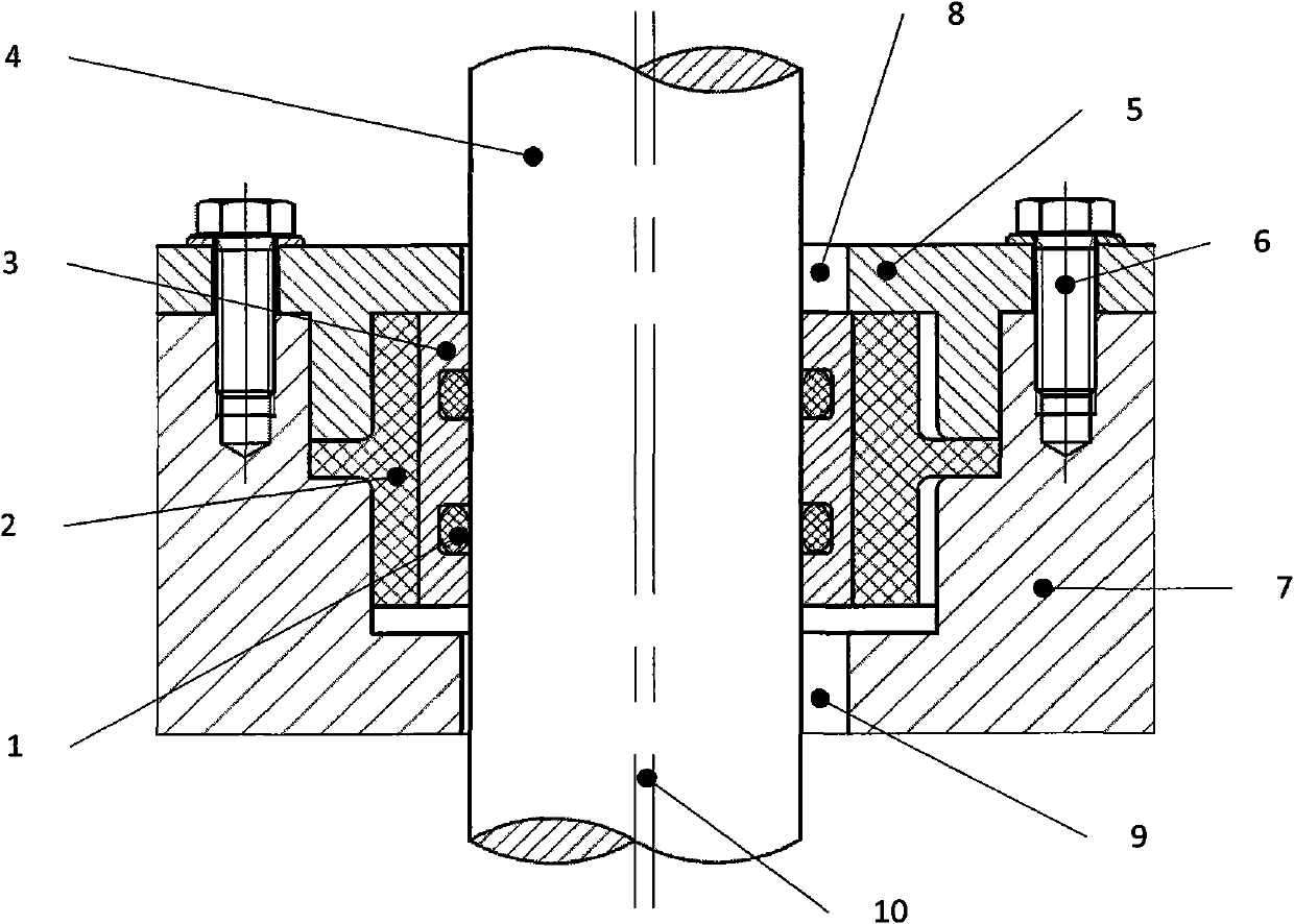
[0013] Such as figure 2 As shown, a floating shaft sealing structure includes a shaft 4, a gland 5, a shell cover 7, a floating ring 2, a shaft sleeve 3 and a sealing ring 1, and the gland 5 and the shell cover 7 are all sleeved on On the shaft 4, the gland 5 is fixed on the shell cover 7 by bolts 6, a ring of bosses is arranged on the lower surface of the gland 5, and a step is provided on the inner wall of the shell cover 7, and the step Located below the boss, the floating ring 2 is cylindrical, with a ring of flanges in the middle of its outer wall, the flanges are pressed between the gland 5 and the shell cover 7, and the shaft sleeves are 4 sets It is arranged on the shaft, and its outer wall is bonded to the inner wall of the floating ring 2. The inner wall of the shaft sleeve 3 is provided with a sealing groove, and the sealing ring 1 is arranged in the sealing gr...


PUM


Abstract

The invention relates to a floating shaft lever sealing structure, comprising a shat lever, a gland, a shell cover, a floating ring, a shaft sleeve and a seal ring; wherein the gland and the shell cover are both sheathed on the shaft lever, the gland is fixed on the cover by virtue of a bolt, the lower surface of the gland is provided with a circle of bosses, the inner wall of the shell cover is provided with a step, the step is arranged below the boss, the floating ring is in a cylinder shape, the middle of the outer wall of the floating ring is provided with a circle of flanges, the flanges are compressed and arranged between the gland and the shell cover, the shaft sleeve is sheathed on the shaft lever, the outer wall thereof is bonded with the inner wall of the floating ring, the inner wall of the shaft sleeve is provided with a seal groove, and the seal ring is arranged in the seal groove. According to the structure, the effects that valve operating torque is reduced and daily maintenance is avoided are achieved, vibration and deflection of the shaft lever are absorbed by the floating ring, the shaft sleeve for placing the seal ring synchronously moves along with the shaft lever, the operation of the seal ring is not influenced by vibration and deflection of the shaft lever, and the effects that seal leakage is avoided and service life is prolonged are achieved.

Description

technical field [0001] The invention relates to shaft sealing technology, in particular to a floating shaft sealing structure. Background technique [0002] The shaft seal is the most prone to "running, popping, dripping, leaking" in valves, compressors, reactors and other equipment. Most of the existing shaft rods adopt the sealing form of packing packing, see figure 1 . When the equipment is working, the shaft has a large vibration and deflection, which causes the axis of the shaft to not coincide with the rotation center, resulting in an excessive eccentricity between them, resulting in seal leakage and reduced service life. At the same time, after the packing is worn out, the gap between the packing, the shaft and the inner wall of the stuffing box increases, and the packing has no ability to automatically compensate the pressing force. As the gap increases, the leakage gradually increases. Therefore, The gland bolts must be tightened frequently, and the daily adjustm...

Claims


Application Information

Patent Timeline
Patent Type & Authority Applications(China)
IPC IPC(8): F16J15/16F16J15/18
Inventor 韩安伟李政宏
Owner SHANGHAI KARON VALVES MACHINERY
Why Eureka
Try Eureka