Floating sealing structure of thrust shaft rod

A floating seal, thrust shaft technology, applied in the direction of engine seals, engine components, mechanical equipment, etc., can solve the problems of unfavorable saving of energy consumption of driving devices, increased operating torque, and large packing pressing force, etc. The effect of routine maintenance, reducing valve operating torque, and prolonging service life

Inactive Publication Date: 2011-04-27
SHANGHAI KARON VALVES MACHINERY +1
View PDF9 Cites 5 Cited by
  • Summary
  • Abstract
  • Description
  • Claims
  • Application Information

AI Technical Summary

Problems solved by technology

The packing pressing force is high, which also leads to the increase of operating torque, which is not conducive to saving the energy consumption required by the driving device

Method used


Image

  • Floating sealing structure of thrust shaft rod
  • Floating sealing structure of thrust shaft rod
  • Floating sealing structure of thrust shaft rod

Examples


Embodiment

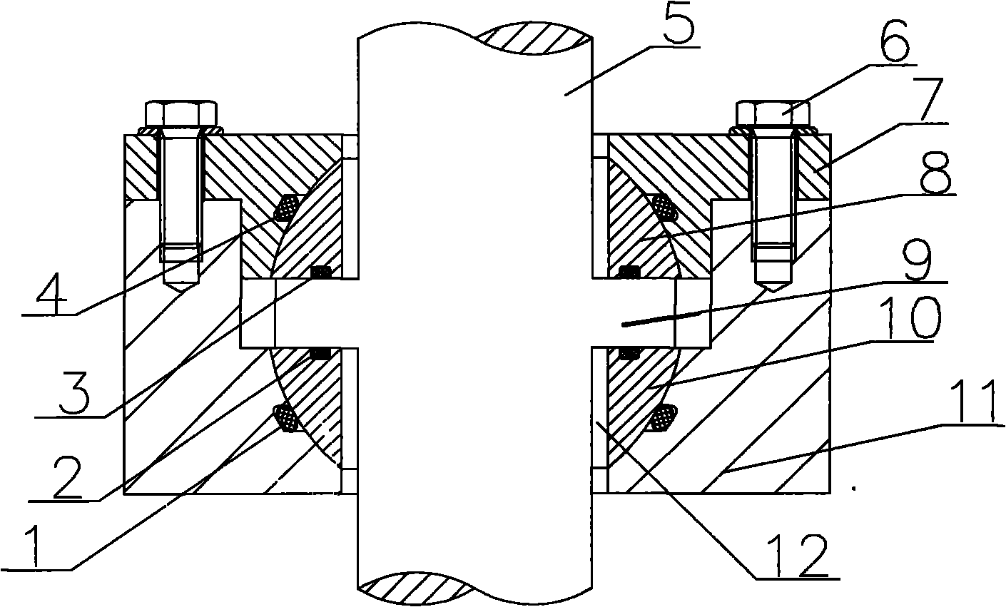
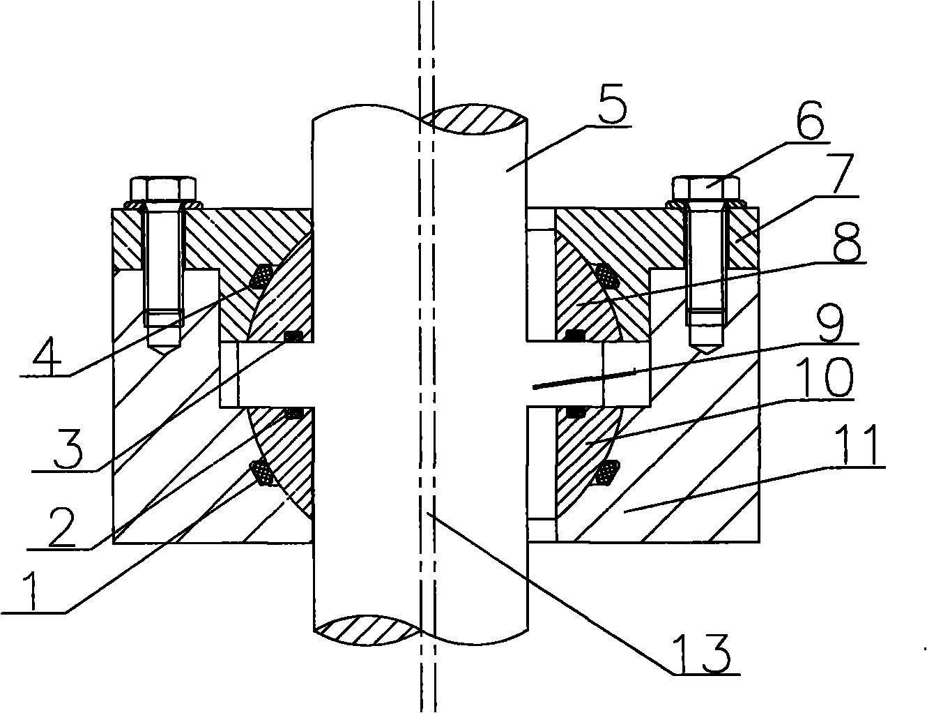
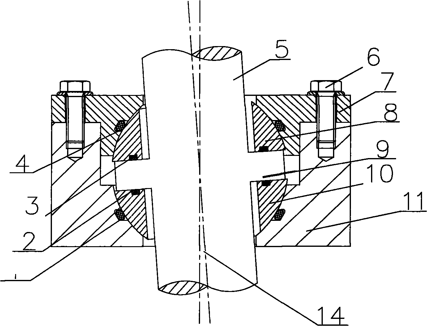
[0020] Such as figure 1 As shown, a floating sealing structure of a thrust shaft includes a first sealing ring 1, a second sealing ring 2, a third sealing ring 3, a fourth sealing ring 4, a shaft 5, bolts 6, a gland 7, The first ball ring 10, the second ball ring 8, and the valve cover 11. The first ball ring 10 and the second ball ring 8 are middle cylindrical holes, and the outer wall surface is a part of the spherical surface. The bottom of the middle hole of the valve cover 11 is a spherical surface, which is matched with the spherical surface of the first ball ring 10, and the upper part is a cylindrical hole. The gland 7 is disc-shaped, the upper flange is fixed on the valve cover 11 with bolts 6 , and the bottom of the middle hole is a spherical surface, which is matched with the spherical surface of the second ball ring 8 . The shaft 5 is a cylindrical rod with a shoulder 9 in the middle, and the shoulder 9 is used to bear the upward and downward axial force when ope...


PUM


Abstract

The invention relates to a floating sealing structure of a thrust shaft rod. The structure comprises a first sealing ring, a second sealing ring, a third sealing ring, a fourth sealing ring, a shaft rod, a bolt, gland, a first ball ring, a second ball ring and a valve cover, wherein the first ball ring and the second ball ring are central cylindrical holes; the bottom of the middle hole of the valve core is a spherical surface matched and connected with the spherical surface of the first ball ring; the upper part of the valve cover is provided with a cylindrical hole; the gland is disc-shaped, an upper flange of the gland is fixed on the valve core through the bolt, and the hollow bottom of the gland is a spherical surface matched and connected with the spherical surface of the second ball ring; and the shaft rod is a cylindrical rod, the middle of which is provided with a shaft shoulder, and the shaft shoulder of the shaft rod is clamped between the first ball ring and the second ball ring. Compared with the prior art, the floating sealing structure has the advantages of good sealing property, long service life and the like.

Description

technical field [0001] The invention relates to a sealing structure, in particular to a floating sealing structure of a thrust shaft. Background technique [0002] The shaft seal is the most prone to "running, popping, dripping, leaking" in valves, compressors, reactors and other equipment. Most of the existing shaft rods are sealed with packing packing. During operation, the shaft rod has relatively large vibration and deflection, which causes the axis of the shaft rod to not coincide with the center of rotation, resulting in an excessive eccentricity between them and sealing Problems of leakage and life reduction. In particular, the valve stem of the hidden stem gate valve has to bear the axial force when the valve is opened and closed at the sealing part, the structure is complex, and the external dimension is large. Simultaneously, the sealing compression force is generated in the radial direction of the shaft, and after the shaft and the seal are worn, it is easy to l...

Claims


Application Information

Patent Timeline
Patent Type & Authority Applications(China)
IPC IPC(8): F16J15/16F16J15/18F16J15/34
Inventor 韩安伟李政宏
Owner SHANGHAI KARON VALVES MACHINERY
Why Eureka
Try Eureka