Inbuilt switch device of three-phase transformer

A technology of three-phase transformers and switchgear, applied in the direction of electric switches, electrical components, circuits, etc., can solve the problems of inability to stop the transformer, control power transmission, etc., and achieve the effect of convenient flowing arc extinguishing

Inactive Publication Date: 2013-01-02
STATE GRID CORP OF CHINA +2
View PDF4 Cites 0 Cited by
  • Summary
  • Abstract
  • Description
  • Claims
  • Application Information

AI Technical Summary

Problems solved by technology

[0002] In the prior art, the well-known technology is that during the use of the transformer, the power on and off of the transformer is realized through external control, so that everyone can operate, so if there is a breach of contract, it cannot be timely It is the shortcoming of the existing technology to realize the power stop and power transmission control for the transformer that violates the contract

Method used


Image

  • Inbuilt switch device of three-phase transformer
  • Inbuilt switch device of three-phase transformer
  • Inbuilt switch device of three-phase transformer

Examples


Embodiment Construction

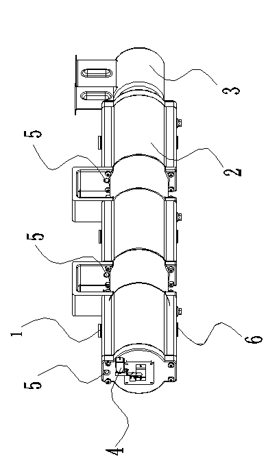
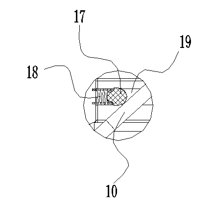
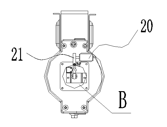
[0022] In order to clearly illustrate the technical features of this solution, the following describes this solution through a specific implementation mode and in conjunction with the accompanying drawings.

[0023] It can be seen from the accompanying drawings that the three-phase transformer built-in switchgear of this program, a three-phase transformer built-in switchgear, includes three incoming wire terminals 1 and three outgoing wire terminals 6, and the three incoming wire terminals Three knife switch movable contacts 10 are arranged on the terminal 1, and three static contacts 13 are arranged on the three outlet terminals 6. The knife switch is arranged in a housing 2 filled with insulating liquid, and the housing 2 is provided with a baffle 7, the outside of the knife switch is provided with a suspended arc extinguishing cover 8, the movable contact 10 of the knife switch moves under the drive of the arc extinguishing cover 8, and the arc extinguishing cover 8 passes t...


PUM


Abstract

The invention provides the technical scheme of an inbuilt switch device of a three-phase transformer. The inbuilt switch device of the three-phase transformer comprises three incoming line connection terminals and three outgoing line connection terminals, wherein three knife-type switch moveable contacts are arranged on the three incoming line connection terminals; three static contacts are arranged on the three outgoing line connection terminals; knife-type switches are arranged in an insulating liquid-accommodating sealed shell; arc extinction shields are arranged outside the knife-type switches; the moveable contacts of the knife-type switches are driven by the arc extinction shields to move; the arc extinction shields are fixedly connected with one another through a connecting rod; a first return spring is fixed between the arc extinction shields and a baffle and is sleeved on the connecting rod; a first electromagnet is arranged at one end of the shell; and a fixed guide rod locking device is arranged at the other end of the shell. The inbuilt switch device of the three-phase transformer is arranged in the transformer to power on and power off the transformer, so arc can be extinguished timely and effectively to avoid accidents.

Description

technical field [0001] The invention relates to a switch, in particular to a switch device built in a three-phase transformer. Background technique [0002] In the prior art, the well-known technology is that during the use of the transformer, the power on and off of the transformer is realized through external control, so that everyone can operate, so if there is a breach of contract, it cannot be timely Realizing the stop and power transmission control of the transformer using electricity in violation of the contract is a deficiency in the prior art. Contents of the invention [0003] The purpose of the present invention is to aim at the deficiencies in the prior art, and provide a technical solution of a three-phase transformer built-in switchgear, the switchgear of this solution is arranged in the transformer, and the power-on and power-off of the transformer are completed inside the transformer, and It can effectively and timely extinguish the arc to avoid accidents....

Claims


Application Information

Patent Timeline
Patent Type & Authority Patents(China)
IPC IPC(8): H01H21/54H01H21/02H01H21/36H01H9/30
Inventor 秦传勇郭哲游春亭宋东升杨卫东秦峥
Owner STATE GRID CORP OF CHINA
Why Eureka
Try Eureka