Protection element

A technology for protecting elements and heating elements, applied in electrical components, emergency protection circuit devices, etc., can solve problems such as inappropriateness, inconvenience, and inability to achieve overvoltage protection, avoiding short-circuit problems, improving reliability, and increasing flow space. Effect with adsorption area

Active Publication Date: 2014-02-12
CYNTEC
View PDF5 Cites 0 Cited by
  • Summary
  • Abstract
  • Description
  • Claims
  • Application Information

AI Technical Summary

Problems solved by technology

[0005] However, since the surface of the insulating layer 130 is almost flat, there is little difference between the maximum height H1 of the electrode layer 160 relative to the substrate 110 and the maximum height H2 of the insulating layer 130 relative to the substrate 110, and the molten metal layer 140 still has a certain viscosity
Therefore, the molten metal layer 140 is not easy to flow, so that the heater 120 cannot effectively fuse the metal layer 140, and cannot meet the requirements of overvoltage protection.
[0006] This shows that above-mentioned existing protective element obviously still has inconvenience and defect in use, and urgently needs to be further improved
In order to solve the above-mentioned problems, the relevant manufacturers have tried their best to find a solution, but no suitable design has been developed for a long time, and generally there is no suitable design that can solve the above-mentioned problems. This is obviously the relevant industry. Urgent problem

Method used


Image

  • Protection element
  • Protection element
  • Protection element

Examples


Embodiment Construction

[0088] In order to further explain the technical means and effects of the present invention to achieve the intended purpose of the invention, the specific implementation, features and effects of the protection element proposed according to the present invention will be described in detail below in conjunction with the drawings and preferred embodiments. rear.

[0089] The aforementioned and other technical contents, features and effects of the present invention will be clearly presented in the following detailed description of preferred embodiments with reference to the drawings. For convenience of description, in the following embodiments, the same elements are denoted by the same numbers.

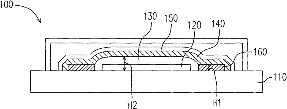
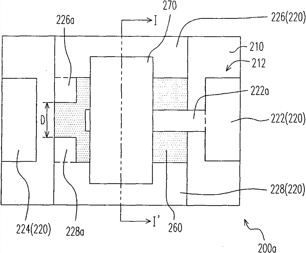
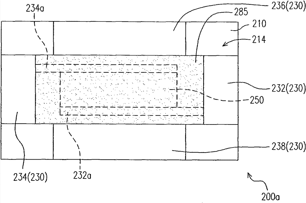
[0090] Figure 2A It is a schematic top view of a protective element according to an embodiment of the present invention. Figure 2B shown as Figure 2A Schematic diagram of the protective element looking up. Figure 2C shown as Figure 2A The schematic cross-sectional view of the pr...


PUM


Abstract

The invention relates to a protection element. The protection element comprises a substrate, an upper electrode, a lower electrode, a terminal electrode, a metal block and a solder layer. The upper electrode is arranged on a first surface of the substrate and is provided with a third sub-electrode and a fourth sub-electrode. The lower electrode is arranged on a second surface of the substrate. The terminal electrode is connected with the upper electrode and the lower electrode. The metal block is arranged on the first surface of the substrate and is connected with the third sub-electrode and the fourth sub-electrode. The solder layer is arranged between the metal block and the third sub-electrode and between the metal block and the fourth sub-electrode. The protection element can effectively prevent overcurrent and overvoltage and is very practical.

Description

technical field [0001] The invention relates to a protection element applied in an electronic device, in particular to a protection element capable of preventing overcurrent and overvoltage. Background technique [0002] In recent years, information technology has advanced by leaps and bounds. Information products such as mobile phones, computers, and personal mobile assistants can be seen everywhere. People's dependence on information products is increasing day by day. However, recently there are often news about the batteries of portable electronic products such as mobile phones exploding during charging and discharging. Therefore, the industry has begun to strengthen protection measures for batteries during charging and discharging to prevent the batteries from exploding due to overvoltage or overcurrent during charging and discharging. [0003] The protection method of the protective element proposed in the prior art is to connect the thermal fuse in the protective ele...

Claims


Application Information

Patent Timeline
Patent Type & Authority Patents(China)
IPC IPC(8): H02H7/20
Inventor 王钟雄罗文翔林鸿铭陈国枢江朗一
Owner CYNTEC
Why Eureka
Try Eureka