Electrical rotary switch

An electrical switch, rotary technology, applied in electrical switches, electrical components, circuits, etc., can solve problems such as affecting the convenience of switch operation and generating sparks

Active Publication Date: 2011-04-27
EWAC HLDG
View PDF3 Cites 23 Cited by
  • Summary
  • Abstract
  • Description
  • Claims
  • Application Information

AI Technical Summary

Problems solved by technology

A known problem with direct current is that when the switch is opened by separating the switch contac

Method used


Image

  • Electrical rotary switch
  • Electrical rotary switch
  • Electrical rotary switch

Examples


Embodiment Construction

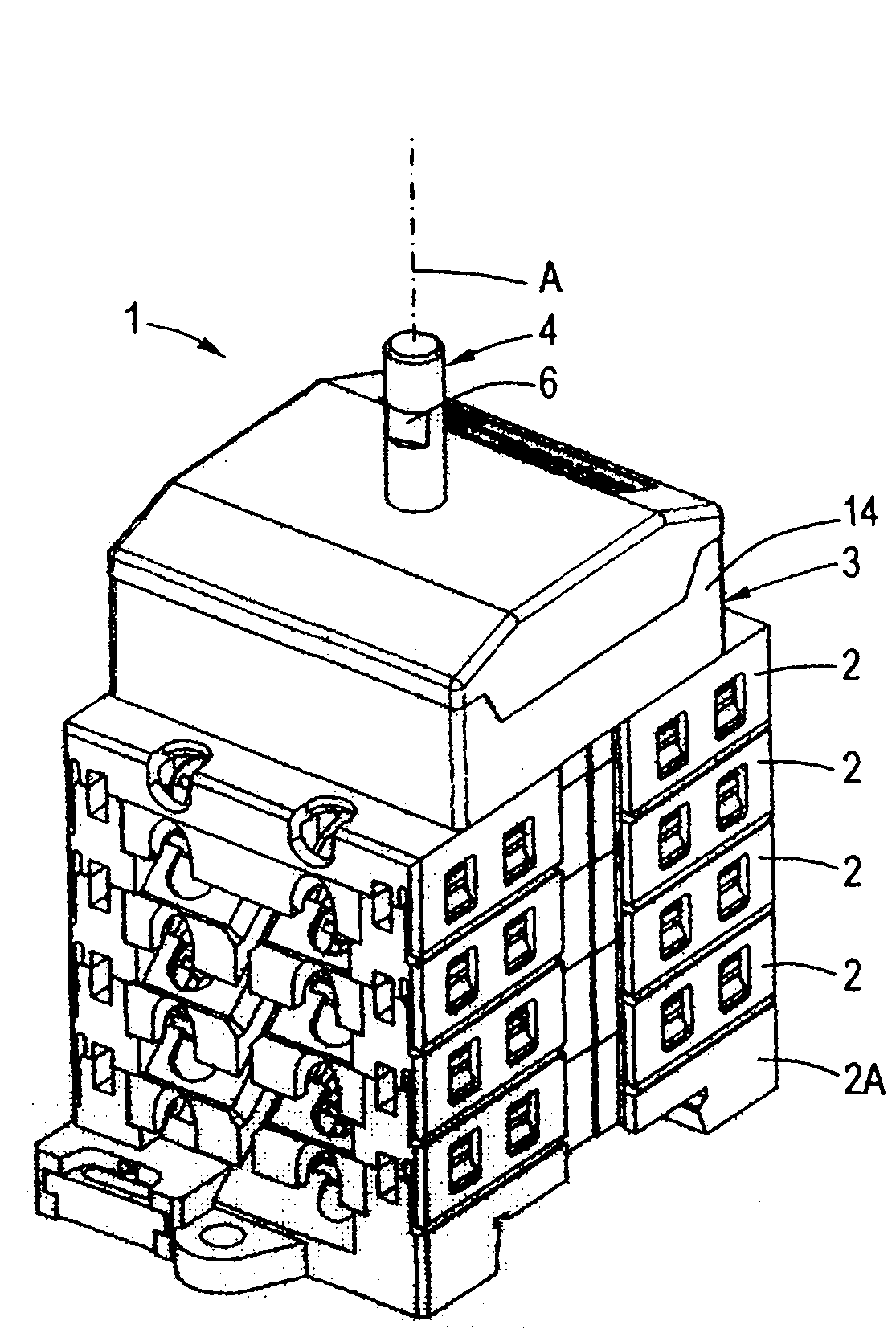
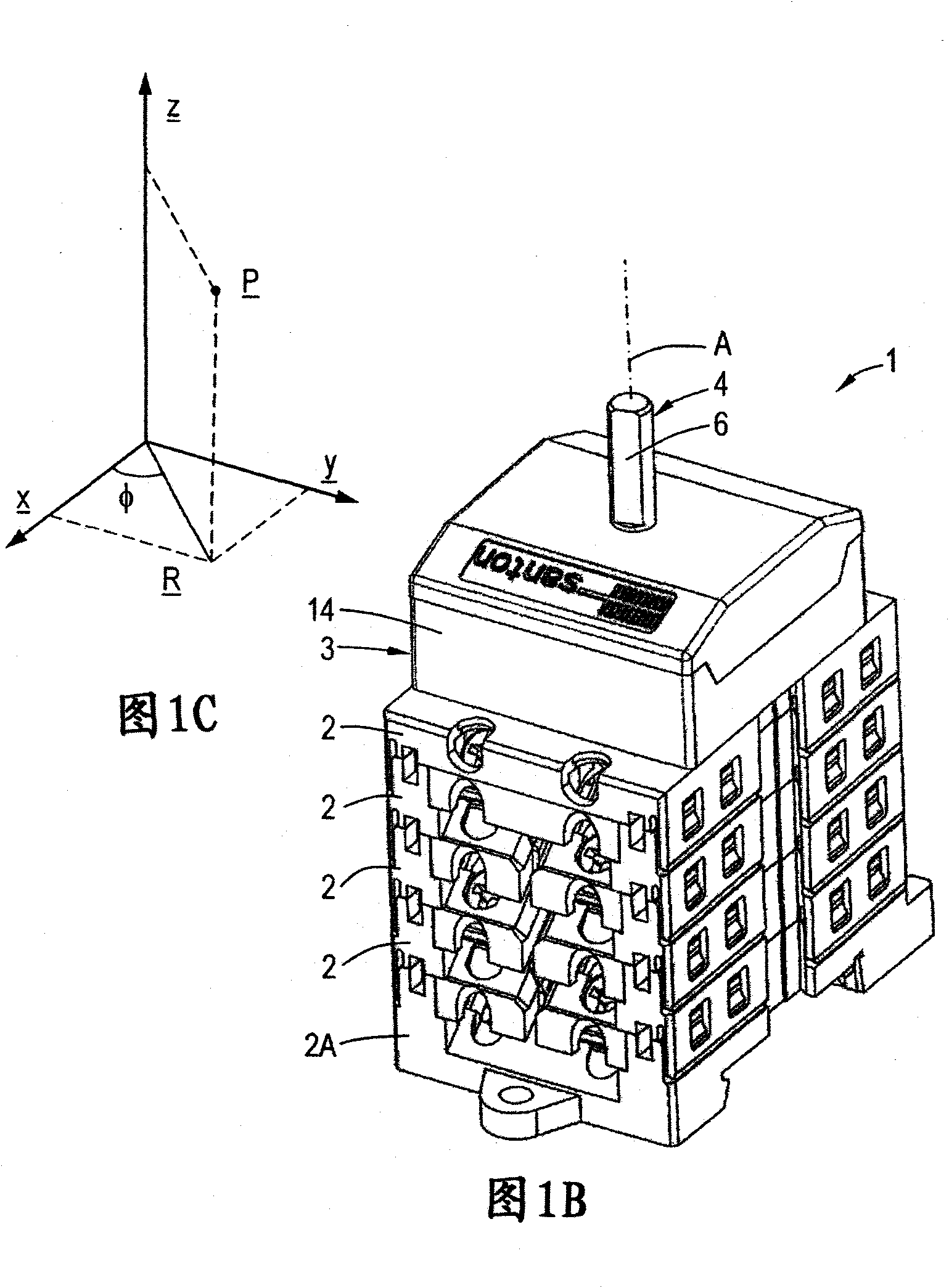
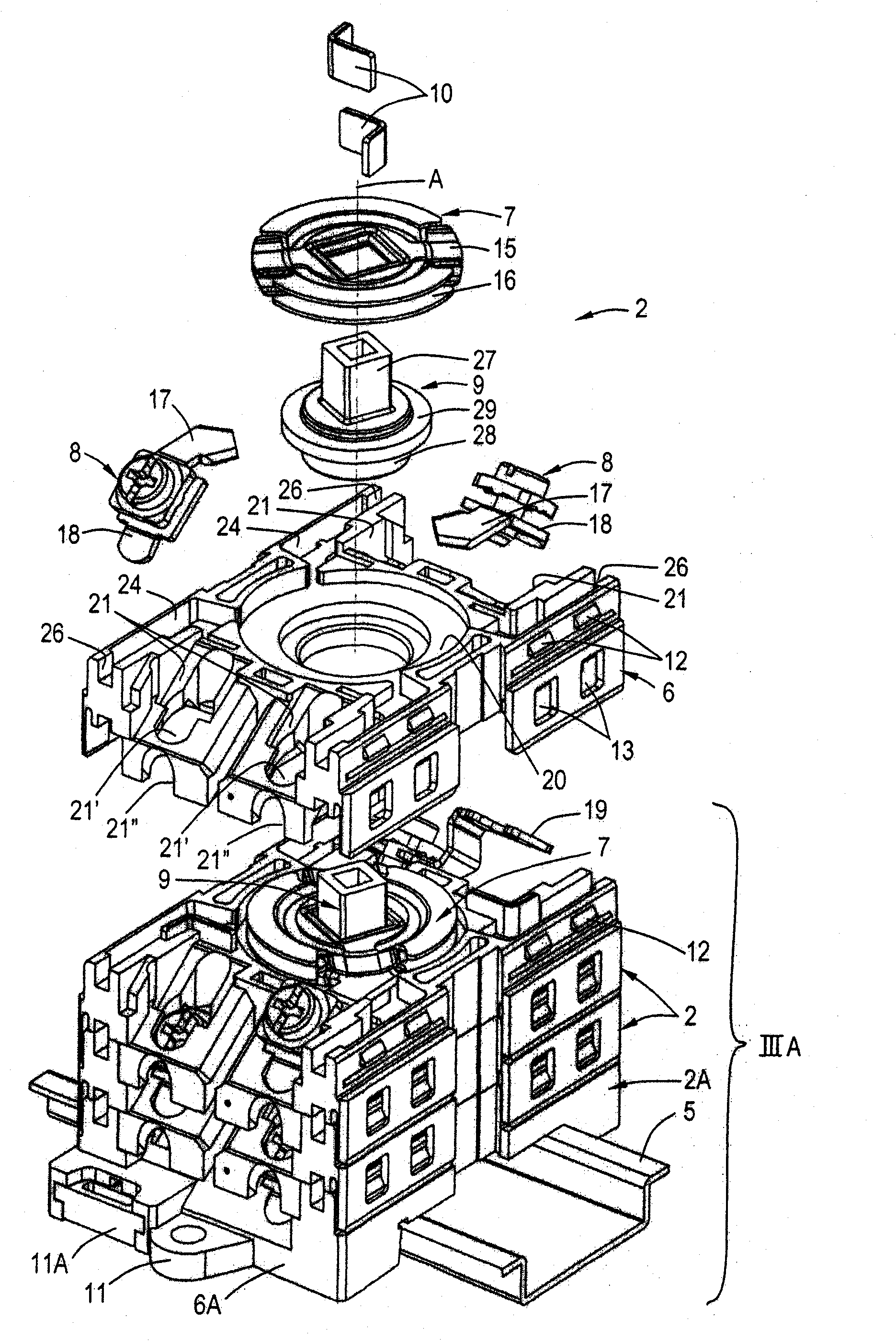
[0045] see Figure 1A and 1B , showing the rotary electrical switch 1. The switch 1 is a modular switch, which includes a plurality of switch modules 2 and rotation control modules 3 stacked together. One of the switch modules 2 is formed as a mounting module 2A for mounting the switch 1 to, for example, a mounting rail 5 ( figure 2 , 3) on the object or device. The switch modules 2, 2A are otherwise substantially identical. The rotary control module comprises a spindle 4 for operating the switch 1 . The spindle is rotatable about an axis A of rotation. For mounting knobs, handles or other operating elements on the spindle 4 , the spindle 4 is provided with a flat surface 6 . Keys, grooves, threads etc. are also conceivable.

[0046] For ease of reference below, Figure 1C A standard coordinate system is depicted; the spatial position of point P can be referred to in Cartesian coordinates ( x , y , z ) and / or referenced to cylindrical coordinates ( R , z )To rep...


PUM


Abstract

A rotary electrical switch comprises at least one rotary contact and a stationary contact. The switch may comprise a housing with a first space for accommodating the rotary contact, a second space for accommodating the stationary contact, and a third space for accommodating the stationary contact. The second space and/or the third space is substantially closed or closable when the stationary contact is arranged in the third space or the second space, respectively. First and second stationary contacts may be arranged offset in the axial direction and/or the angular direction with respect to the axis of rotation, with first and second rotary contacts being arranged for concurrently contacting the first and second stationary contacts, respectively, in a first rotary orientation about the common axis of rotation. An improved locking spring is also provided.

Description

technical field [0001] The present invention relates to the field of rotary electrical switches, and in particular to rotary switches for switching high power. Background technique [0002] In general, rotary electrical switches comprising a rotary contact and a plurality of stationary contacts are known. Such a switch may include multiple layers, each layer including a rotating contact and multiple stationary contacts for switching multiple currents simultaneously. [0003] Rotary electrical switches are mainly used to switch direct current. A known problem with direct current is that when the switch is opened by separating the switch contacts, a spark is created between the contacts. Sparks can also be produced when the AC power is cut when the current is non-zero. The spark creates an explosive cloud of hot plasma that is usually corrosive and conductive. Plasma clouds or spark plumes can thereby damage nearby objects and / or create or cause short circuits. Sparks and...

Claims


Application Information

Patent Timeline
IPC IPC(8): H01H19/64
CPCH01H19/24H01H19/64H01H1/2041H01H19/02
Inventor R·C·韦伯M·W·雷德林
Owner EWAC HLDG
Why Eureka
Try Eureka