Supercharge Your Innovation With Domain-Expert AI Agents!

Electrical and optical system and methods for monitoring erosion of electrostatic chuck edge bead materials

An electrostatic chuck and electrical technology, applied in the direction of electrical components, circuits, discharge tubes, etc., can solve the problems of particle generation, harmful effects on device yield, etc.

Active Publication Date: 2011-04-27
LAM RES CORP
View PDF0 Cites 0 Cited by
  • Summary
  • Abstract
  • Description
  • Claims
  • Application Information

AI Technical Summary

Problems solved by technology

[0010] Further, direct exposure of the bond line to the plasma may result in the generation of particulates, which may have a detrimental effect on device yield
Erosion of this bond line prevents refurbishment for further beading and impacts final component life

Method used


Image

  • Electrical and optical system and methods for monitoring erosion of electrostatic chuck edge bead materials
  • Electrical and optical system and methods for monitoring erosion of electrostatic chuck edge bead materials
  • Electrical and optical system and methods for monitoring erosion of electrostatic chuck edge bead materials

Examples


Embodiment Construction

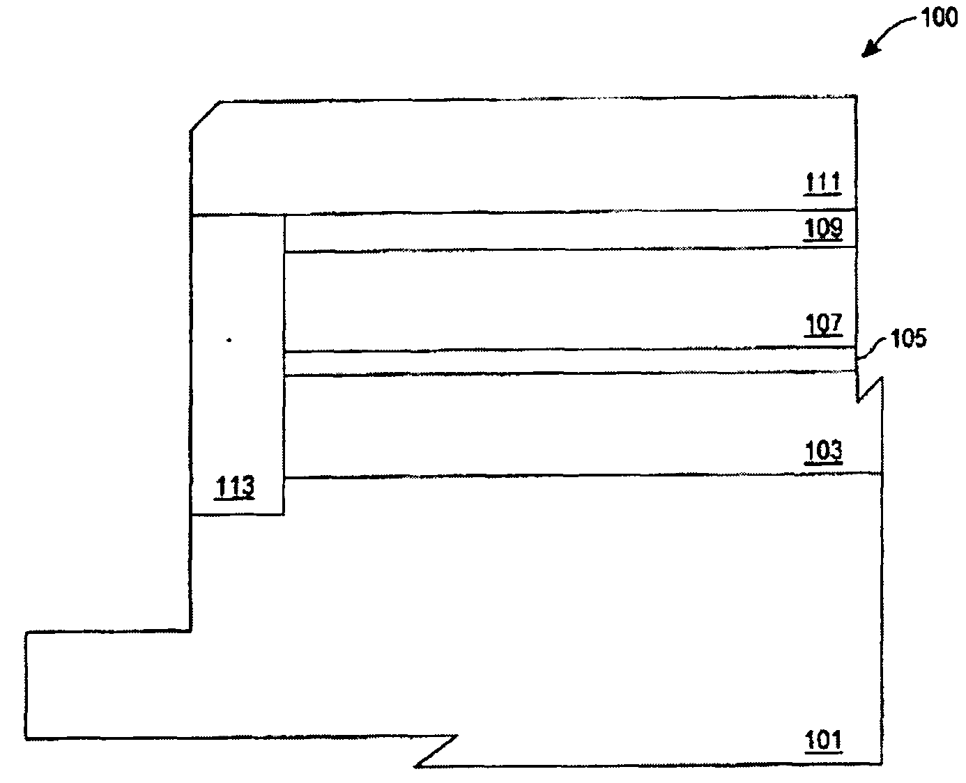
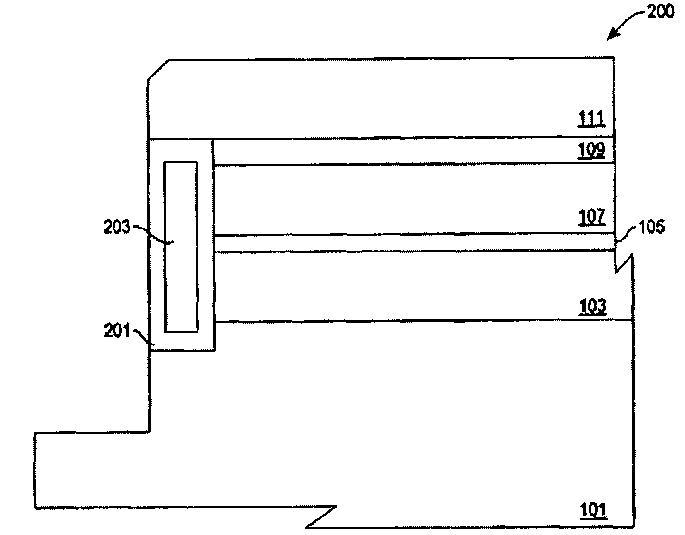
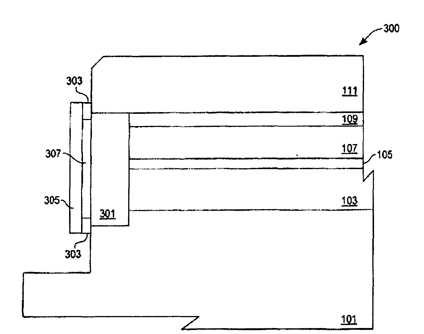
[0021] The various embodiments discussed below disclose a tool for monitoring when the edge adhesive seal inside the ESC is corroded, thereby protecting the heater and other adhesive layers. Various embodiments disclose the monitoring tape or layer in the edge bead of the ESC, which has an independent erosion indicator or an indicator combined with various optical or electrical monitoring instruments. When the monitoring layer is exposed to plasma, it interacts with plasma species to produce volatile chemicals that can be detected by, for example, an optical emission spectroscopy (OES) system.

[0022] In other embodiments, the change of the monitoring layer can be detected by a simple reflectance or optical scattering system. The design of these and related optical measurement systems is known in the art.

[0023] Alternatively, because the plasma erosion reaction changes the measurement resistance of the conductive layer, the resistance of the monitoring layer can be measured. ...


PUM


Abstract

A disclosed device comprises an edge bonding seal configured to be mounted to an edge bead of the electrostatic chuck. The edge bonding seal includes a monitoring layer comprised of a first material configured to either emit a species capable of being optically monitored or having an electrical resistance value capable of being monitored, or both. The edge bonding seal further includes an edge bonding layer configured to be interspersed at least between the monitoring layer and the plasma environment. The edge bonding layer is comprised of a second material susceptible to erosion due to reaction with the plasma environment and configured to expose the monitoring layer to the plasma environment upon sufficient exposure to the plasma environment.

Description

[0001] Priority statement [0002] This application claims the priority of the US patent application with application number 12 / 126,625 and the filing date of May 23, 2008, the full text of which is incorporated herein by reference. Technical field [0003] The present invention generally relates to the field of process equipment used in semiconductor, data storage, flat panel display, and related or other industries. In particular, the present invention relates to systems and methods for monitoring the erosion of edge bead materials of electrostatic chucks used in plasma-based process tools. Background technique [0004] Since semiconductor devices were first introduced decades ago, the geometry (ie, integrated circuit design rules) of these devices has been significantly reduced in size. Integrated circuits (ICs) generally follow "Moore's Law", which means that the number of devices manufactured on a single integrated circuit chip doubles every two years. Current IC manufacturin...

Claims


Application Information

Patent Timeline
IPC IPC(8): H01L21/683H01L21/687H01L21/66H01L21/3065
CPCH01J37/32642H01J37/32972H01J37/3299H01J37/32935
Inventor 布拉德利·J·霍华德埃里克·佩普李思文
Owner LAM RES CORP
Features
  • R&D
  • Intellectual Property
  • Life Sciences
  • Materials
  • Tech Scout
  • Unparalleled Data Quality
  • Higher Quality Content
  • 60% Fewer Hallucinations
Learn More