Plug of a plug-type connector

A connector and contact board technology, applied in the direction of connection, connecting device parts, conductive connection, etc., can solve the problem that the plug-in connector cannot meet the needs, and achieve the effect of convenient assembly

Inactive Publication Date: 2011-04-27
SIEMENS MOBILITY GMBH
View PDF8 Cites 6 Cited by
  • Summary
  • Abstract
  • Description
  • Claims
  • Application Information

AI Technical Summary

Problems solved by technology

As the number of poles of the contact plate 6 continues to increase, this existing plug of the plug-in connector cannot meet the needs.

Method used


Image

  • Plug of a plug-type connector
  • Plug of a plug-type connector
  • Plug of a plug-type connector

Examples


Embodiment Construction

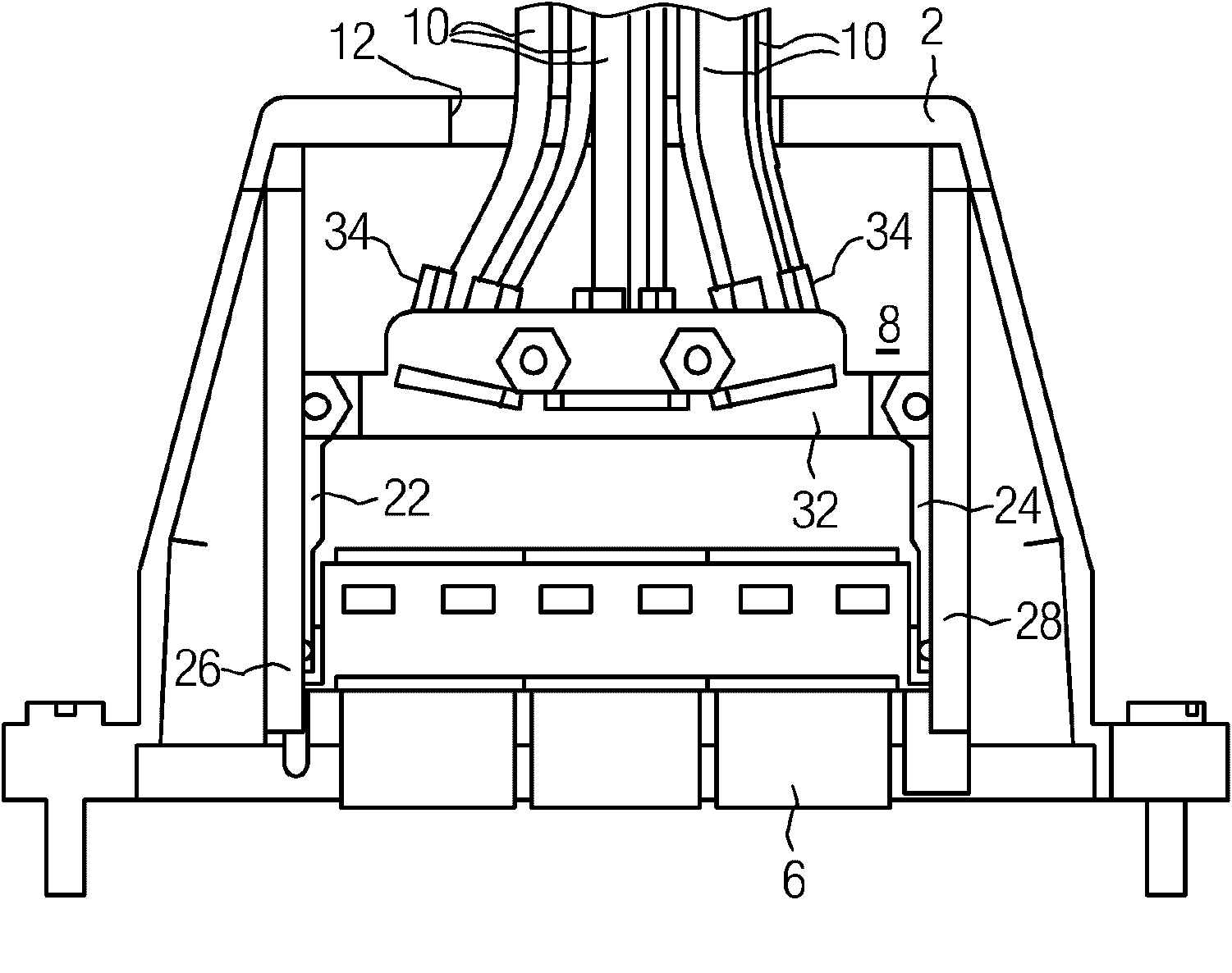
[0015] figure 2 Shown is the plug of the present invention. The difference between the plug of the present invention and the aforementioned plugs of the same type is that two shielding clamping plates 30 and 32 are provided on the shielding frame 8 instead of one clamping plate. In addition, three cable clamps 34 are provided between the two shield clamp plates 30 and 32. Each cable clamp 34 can be connected to a group of multi-core shielded cables 10.

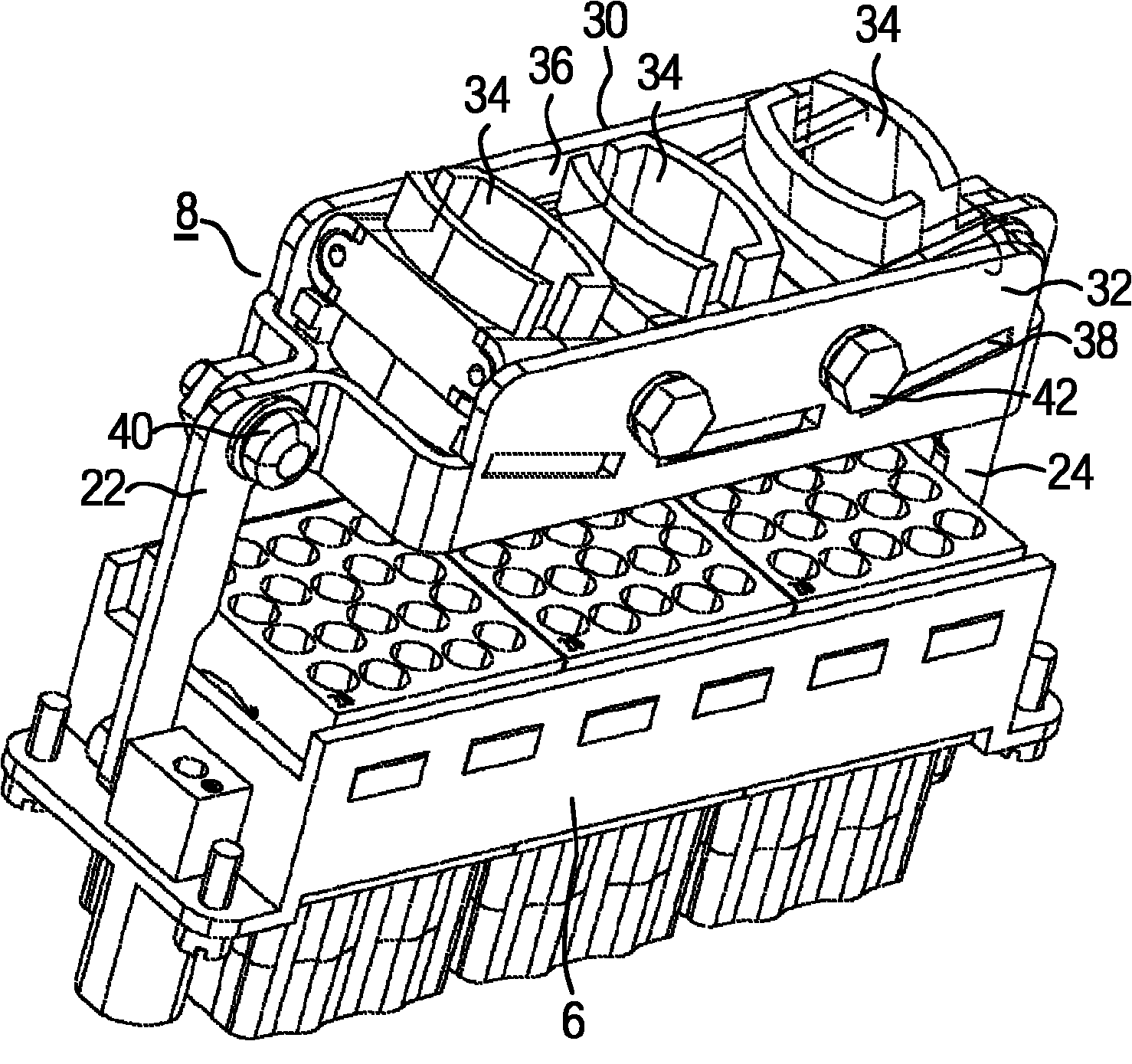
[0016] To facilitate the understanding of the present invention, image 3 Only the contact plate 6 and the shielding frame 8 designed according to the invention are shown in a perspective view. It can be seen from the perspective view that the two shielding clamp plates 30 and 32 form a receiving area 36. Three cable clamps 34 are provided in this receiving area, which are arranged along a concave line relative to the contact plate 6. This can better guide the group of multi-core shielded cables 10 through the opening 12 on t...


PUM


Abstract

The invention relates to a plug, in particular a high-pole plug, of a plug-type connector for a number of multi-core, screened cables (10), of which the lines are electrically conductively connected to contacts of a contact strip (6) and of which the cable screens are electrically conductively connected to a screen support (8), wherein the contact strip (6) and the screen support (8) are arranged physically at a distance from one another in a hood (2), and wherein the screen support (8) is electrically connected to an earth connection of the plug. According to the invention, two screen clips (30, 32) are provided as the screen support (8), it being possible for these screen clips to be connected to one another in a releasable manner and these screen clips being formed in such a way that they form an accommodation region (36) for cable terminals (34) which can be clamped between these screen clips (30, 32). Therefore, a plug of this type can accommodate a contact strip (6) with a high pole number, without the dimensions of the hood (2) of said plug having to be modified.

Description

Technical field [0001] The invention relates to a plug of a plug-in connector according to the preamble of claim 1. Background technique [0002] figure 1 Shown is a plug of the same type of plug-in connector used for multiple multi-core shielded cables, especially multi-pole plugs, which are available on the market. In the figure, reference symbol 2 denotes an outer cover, 6 denotes a contact plate, 8 denotes a shield frame, and 10 denotes a multi-core shielded cable. The contact plate 6 with the shielding frame 8 and the outer cover 2 can be connected to each other in a detachable manner and together constitute the same type of plug of a plug-in connector. The outer cover 2 has an opening 12 for the multi-core shielded cable 10 to be inserted into the outer cover 2. The contact plate 6 can be designed as a plug-type contact plate or a socket-type contact plate. Each cable 10 is electrically conductively connected to a clamping plate of the shielding frame 8 through a cable c...

Claims


Application Information

Patent Timeline
Patent Type & Authority Applications(China)
IPC IPC(8): H01R13/595H01R13/6581H01R13/516H01R13/658
CPCH01R13/516H01R13/6593H01R9/032H01R13/658H01R13/5804H01R13/595H01R13/6588H01R13/65912
Inventor 曼弗雷德·海泽彼得·劳贝欧根·诺普彭伯格
Owner SIEMENS MOBILITY GMBH
Why Eureka
Try Eureka