Overcurrent detection circuit

A detection circuit and overcurrent technology, applied in the direction of measuring current/voltage, measuring device, measuring electrical variables, etc., can solve problems such as poor accuracy of overcurrent discharge threshold, and achieve the effect of reducing the number of mismatch series

Active Publication Date: 2012-08-29
WUXI ZGMICRO ELECTRONICS CO LTD
View PDF0 Cites 0 Cited by
  • Summary
  • Abstract
  • Description
  • Claims
  • Application Information

AI Technical Summary

Problems solved by technology

More stages of mismatch lead to poorer accuracy of overcurrent discharge threshold

Method used


Image

  • Overcurrent detection circuit
  • Overcurrent detection circuit
  • Overcurrent detection circuit

Examples


Embodiment Construction

[0027] Reference herein to "one embodiment" or "an embodiment" refers to a particular feature, structure or characteristic that can be included in at least one implementation of the present invention. "In one embodiment" appearing in different places in this specification does not all refer to the same embodiment, nor is it a separate or selective embodiment that is mutually exclusive with other embodiments.

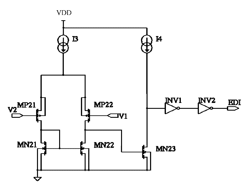
[0028] see Figure 4 As shown, it shows the structure of an embodiment of the overcurrent detection circuit of the present invention. As shown in the figure, the overcurrent detection circuit of the present invention includes a first voltage input circuit, a second voltage input circuit and a comparator.

[0029] The first voltage input circuit includes a first current source I31, one end of the first current source I31 is connected to the power supply V, and the other end of the first current source I31 is connected to the source of the first transistor MP31 through a r...


PUM


Abstract

The invention provides an overcurrent detection circuit which comprises a first input voltage circuit, a second input voltage circuit and a comparator, wherein the first input voltage circuit and the second input voltage circuit respectively provide a first input voltage and a second input voltage to a first input end and a second input end of the comparator; and the comparator has an input deviation, and compares the first input voltage and the second input voltage to output a comparative result signal.

Description

【Technical field】 [0001] The invention relates to the field of electronic circuits, in particular to a discharge overcurrent detection circuit in a battery protection circuit. 【Background technique】 [0002] figure 1 It is a structural diagram of a lithium battery. The lithium battery is composed of a battery protection circuit and a battery cell. The battery protection circuit includes a battery protection chip and power device MOS tubes MD and MC. The battery protection chip is inside the dotted line box. The battery protection chip includes an overcharge detection circuit, an overcurrent detection circuit, a charging overcurrent detection circuit, a discharge overcurrent detection circuit, and a control circuit. When there is no abnormal state after the lithium battery is connected to the load RL, MC and MD are in the conduction state, and the lithium battery discharges the load RL. The discharge current is shown by the arrow in the figure. When MC and MD are conducting,...

Claims


Application Information

Patent Timeline
Patent Type & Authority Patents(China)
IPC IPC(8): G01R19/165
Inventor 王钊
Owner WUXI ZGMICRO ELECTRONICS CO LTD
Why Eureka
Try Eureka