
Light guide plate and manufacturing method thereof

A manufacturing method and a technology of a light guide plate, which are applied in the field of light guide plates, can solve problems such as easy occurrence of offset, decrease in optical precision of an optical element array, and inability to obtain an optical element array, etc., and achieve the effect of a uniform surface light source

Inactive Publication Date: 2011-05-04
苏州茂立光电科技有限公司
View PDF12 Cites 3 Cited by
  • Summary
  • Abstract
  • Description
  • Claims
  • Application Information

AI Technical Summary

Problems solved by technology

However, the punching process is prone to offset, which will reduce the optical precision of the formed optical element array, and it is impossible to obtain an optical element array that can well scatter light

Method used


Image

  • Light guide plate and manufacturing method thereof
  • Light guide plate and manufacturing method thereof
  • Light guide plate and manufacturing method thereof

Examples


Embodiment Construction

[0021] Below in conjunction with accompanying drawing and specific embodiment the present invention is described in further detail:

[0022] The invention provides a manufacturing method of a light guide plate, which can easily form an array of optical elements with high optical precision on the side (light incident surface) of the light guide plate with extremely thin thickness.

[0023] The invention provides a light guide plate, which can improve the yield and precision of the light guide plate manufacturing process.

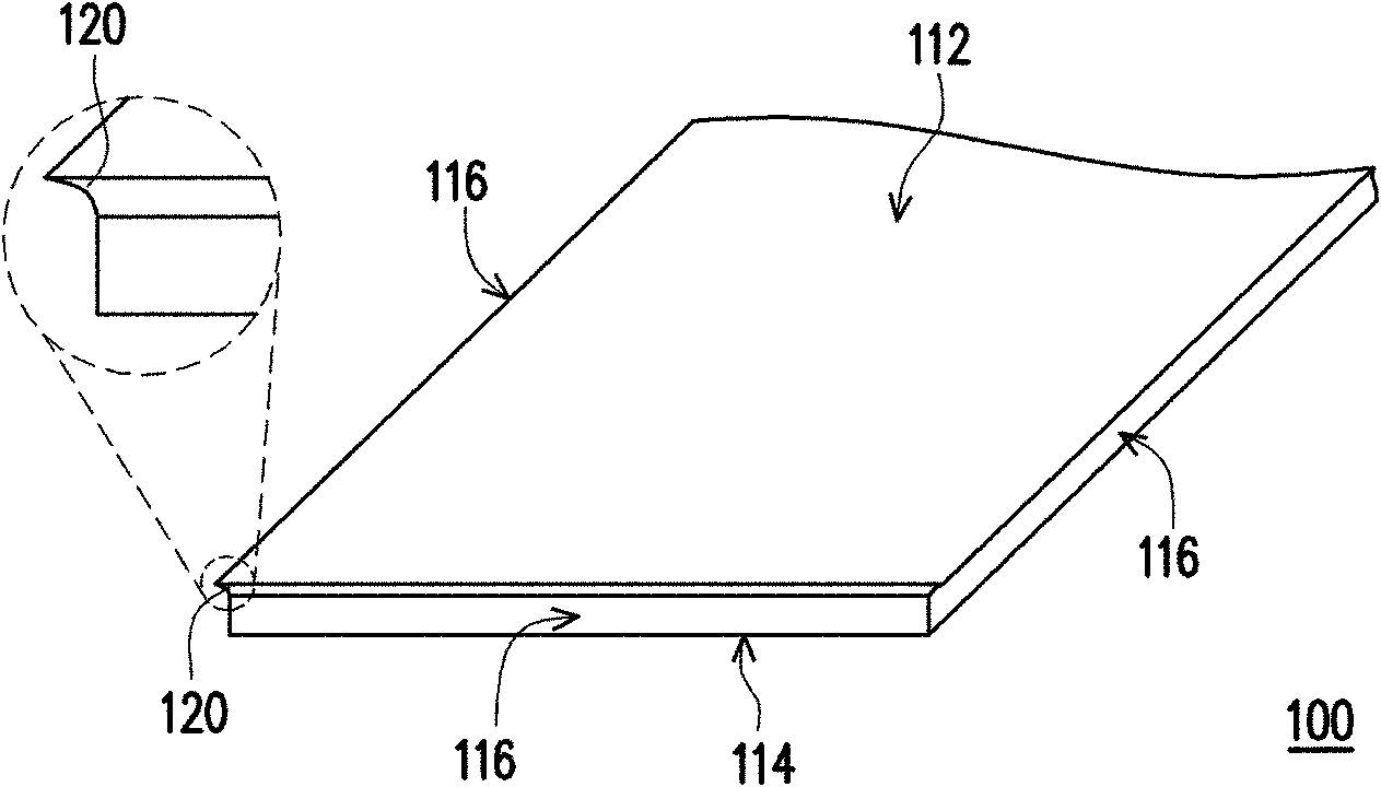
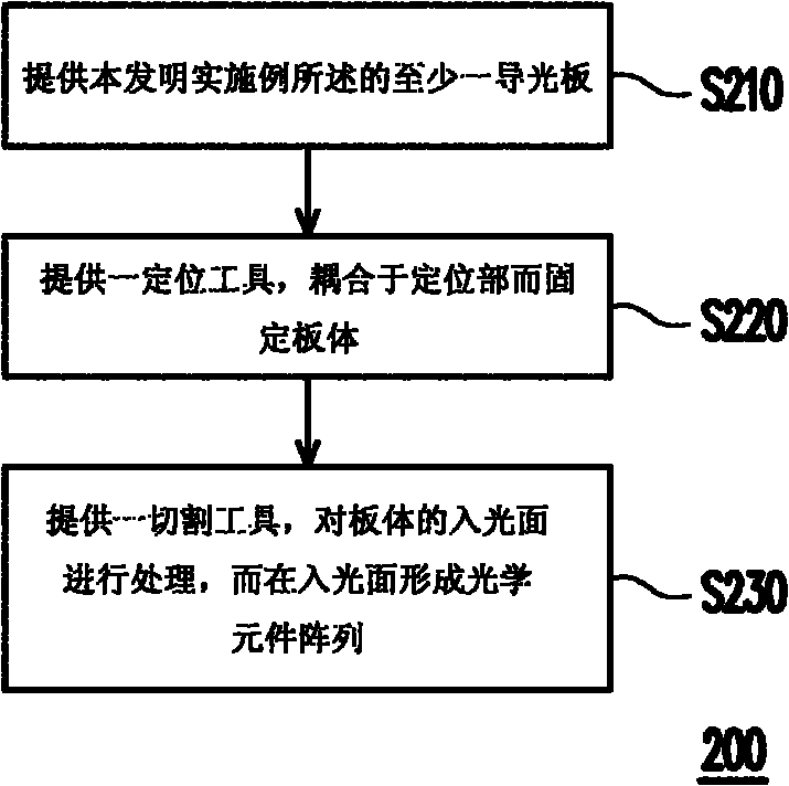
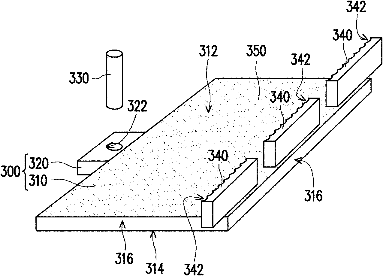
[0024] The invention provides a method for manufacturing a light guide plate, which includes the following steps. Firstly, at least one light guide plate is provided, and the light guide plate includes: a plate body and at least one positioning portion connected to the plate body, wherein the plate body has a light-emitting surface, a light-reflecting surface facing the light-emitting surface, and a contact light-emitting surface and a light-reflecting surfac...


PUM


Abstract

The invention relates to a light guide plate and a manufacturing method thereof. The light guide plate comprises a plate body and at least one positioning part, wherein the plate body is provided with a light emergent surface, a reflective surface opposite to the light emergent surface and at least one light incident surface which is contacted with the light emergent surface and the reflective surface; and the positioning part is connected to at least one side of the plate body. The method for manufacturing the light guide plate is realized through the following steps: providing at least one light guide plate which comprises a plate body and at least one positioning plate connected to the plate body, wherein the plate body is provided with the light emergent surface, the reflective surface opposite to the light emergent surface and at least one light incident surface contacted with the light emergent surface and the reflective surface; providing a positioning tool which is coupled to the positioning part to fix the plate body; and providing at least one cut tool which treats the light incident surface of the plate body and forms an optical element array on the light incident side. The invention has the beneficial effects that: light can enter into the light incident surface uniformly to provide a uniform area light source.

Description

technical field [0001] The invention relates to a light guide plate, in particular to the structure of the light guide plate and its manufacturing method. Background technique [0002] Thin liquid crystal display devices generally use a backlight module composed of light emitting diodes and light guide plates to generate surface light sources to illuminate the liquid crystal display panel. Generally speaking, light emitting diodes as point light sources are disposed on the side (light incident surface) of the light guide plate to provide light incident into the light guide plate. However, in order to smoothly enter the light from the side of the light guide plate into the light guide plate, the light emitting diodes must be arranged within a specific angle range relative to the side of the light guide plate, which makes assembly difficult. In addition, as the thickness of the light guide plate becomes thinner, the area of ​​the side of the light guide plate becomes smaller,...

Claims


Application Information

Patent Timeline
IPC IPC(8): G02B6/00
Inventor 李国成
Owner 苏州茂立光电科技有限公司
Learn More