Light guide unit and backlight module
A technology of light guide unit and backlight module, which is applied in the direction of optical components, optics, light guide, etc., and can solve the problems of increasing cost and light loss
- Summary
- Abstract
- Description
- Claims
- Application Information
AI Technical Summary
Problems solved by technology
Method used
Image
Examples
no. 1 example
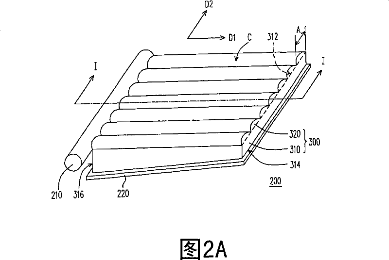
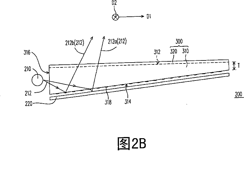
[0023] Figure 2A is a three-dimensional schematic diagram of the backlight module of the first embodiment of the present invention, Figure 2B for Figure 2A The cross-sectional schematic diagram of the backlight module along the I-I line, while Figure 2C for Figure 2A A perspective view of the light guide unit in with its first surface facing forward. Please refer to Figure 2A to Figure 2C , the backlight module 200 of this embodiment includes a light guide unit 300 and a light emitting element 210 . The light guide unit 300 includes a light guide plate 310 and several lenticular lenses 320 . The light guide plate 310 has a first surface 312 , a second surface 314 and a light incident surface 316 . The first surface 312 is opposite to the second surface 314 , and the light incident surface 316 connects the first surface 312 and the second surface 314 . The lenticular lenses 320 are disposed on the first surface 312 . Each lenticular lens 320 extends along a first ...
no. 2 example
[0030] image 3 It is a three-dimensional schematic view of the backlight module according to the second embodiment of the present invention. Please refer to image 3 , the backlight module 200a of this embodiment is the same as the above-mentioned backlight module 200 (please refer to Figure 2A ) are similar, and the differences between the two are described below. In the light guide unit 300a of the backlight module 200a of this embodiment, some of the curved surfaces C1 of these lenticular lenses 320a are convex surfaces, and some of the curved surfaces C1' of these lenticular lenses 320a' are concave surfaces, and these curved surfaces C1 and these curved surfaces C1' Alternately arranged in the second direction D2. In this embodiment, these curved surfaces C1 and these curved surfaces C1' form a one-dimensional sinusoidal surface. However, in other embodiments, the curved surface C1 can also be a cylindrical surface, an elliptical cylindrical surface, or a convex sur...
no. 3 example
[0032] Figure 4 It is a perspective view of the light guide unit of the backlight module according to the third embodiment of the present invention with its first surface facing forward. Please refer to Figure 4 , the light guide unit 300b of the backlight module of this embodiment and the above light guide unit 300 (such as Figure 2C shown) are similar, and the differences between the two are described below. In the light guide unit 300b of the present embodiment, the number density of the diffused dots 318 increases gradually as the distance from the light incident surface 316 increases. In this way, the light guide unit 300b can guide the light away from the light incident surface 316, so that the backlight module can provide a uniform surface light source. In addition, in this embodiment, the widths W1' of the diffused dots 318 in the first direction D1 may be substantially the same, and the widths W2' of the diffused dots 318 in the second direction D2 may also be s...
PUM
 Abstract
Description
Claims
Application Information
 - R&D
- Intellectual Property
- Life Sciences
- Materials
- Tech Scout
- Unparalleled Data Quality
- Higher Quality Content
- 60% Fewer Hallucinations
Browse by: Latest US Patents, China's latest patents, Technical Efficacy Thesaurus, Application Domain, Technology Topic, Popular Technical Reports.
© 2025 PatSnap. All rights reserved.Legal|Privacy policy|Modern Slavery Act Transparency Statement|Sitemap|About US| Contact US: help@patsnap.com


