
Back-light module and liquid crystal display

A backlight module and reflective technology, which is applied in the direction of instruments, optics, transistors, etc., can solve the problem of not being able to ensure no gaps, and achieve good display quality

Inactive Publication Date: 2009-04-08
高智发明基金第82有限责任公司
View PDF5 Cites 0 Cited by
  • Summary
  • Abstract
  • Description
  • Claims
  • Application Information

AI Technical Summary

Problems solved by technology

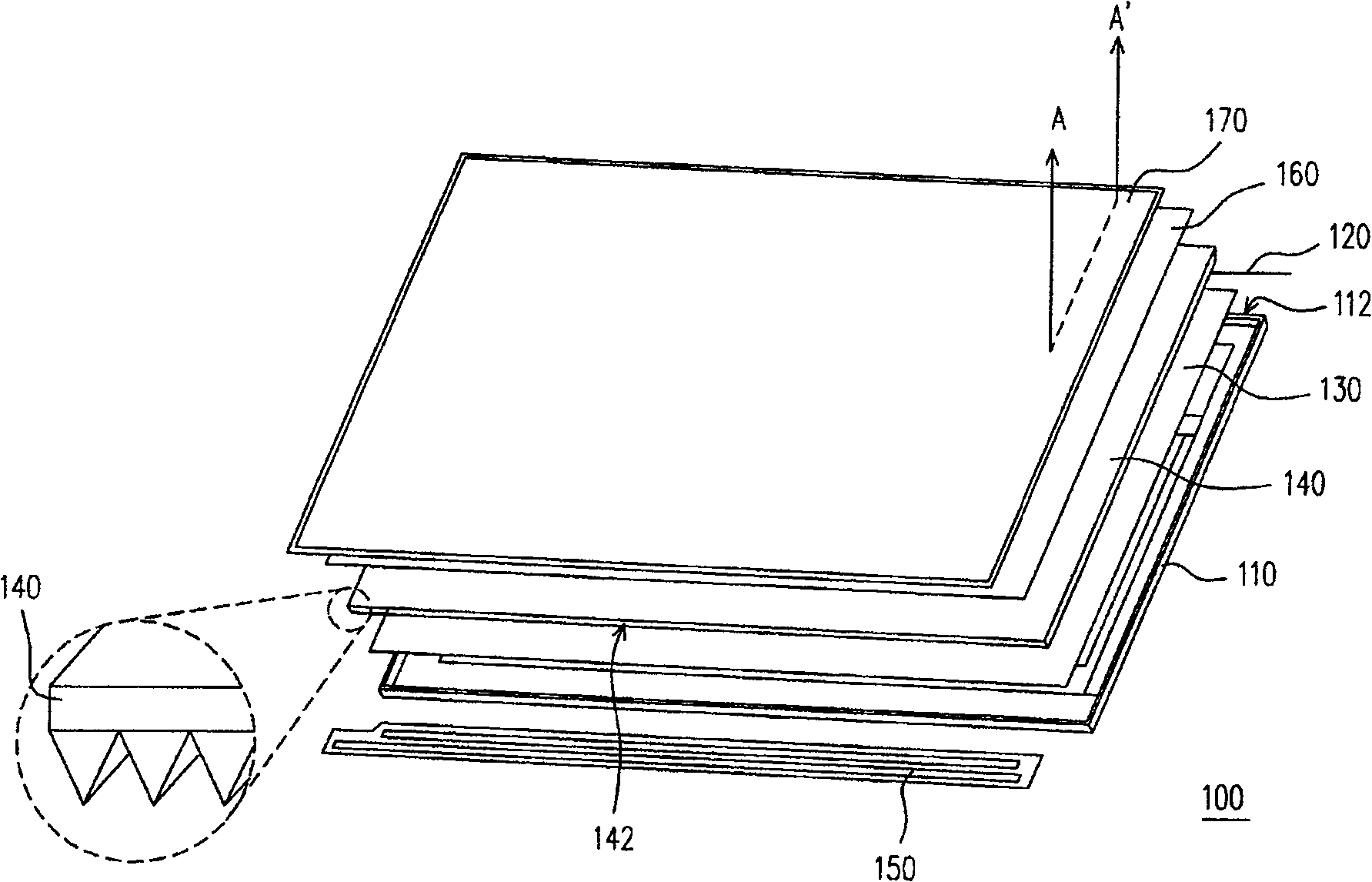
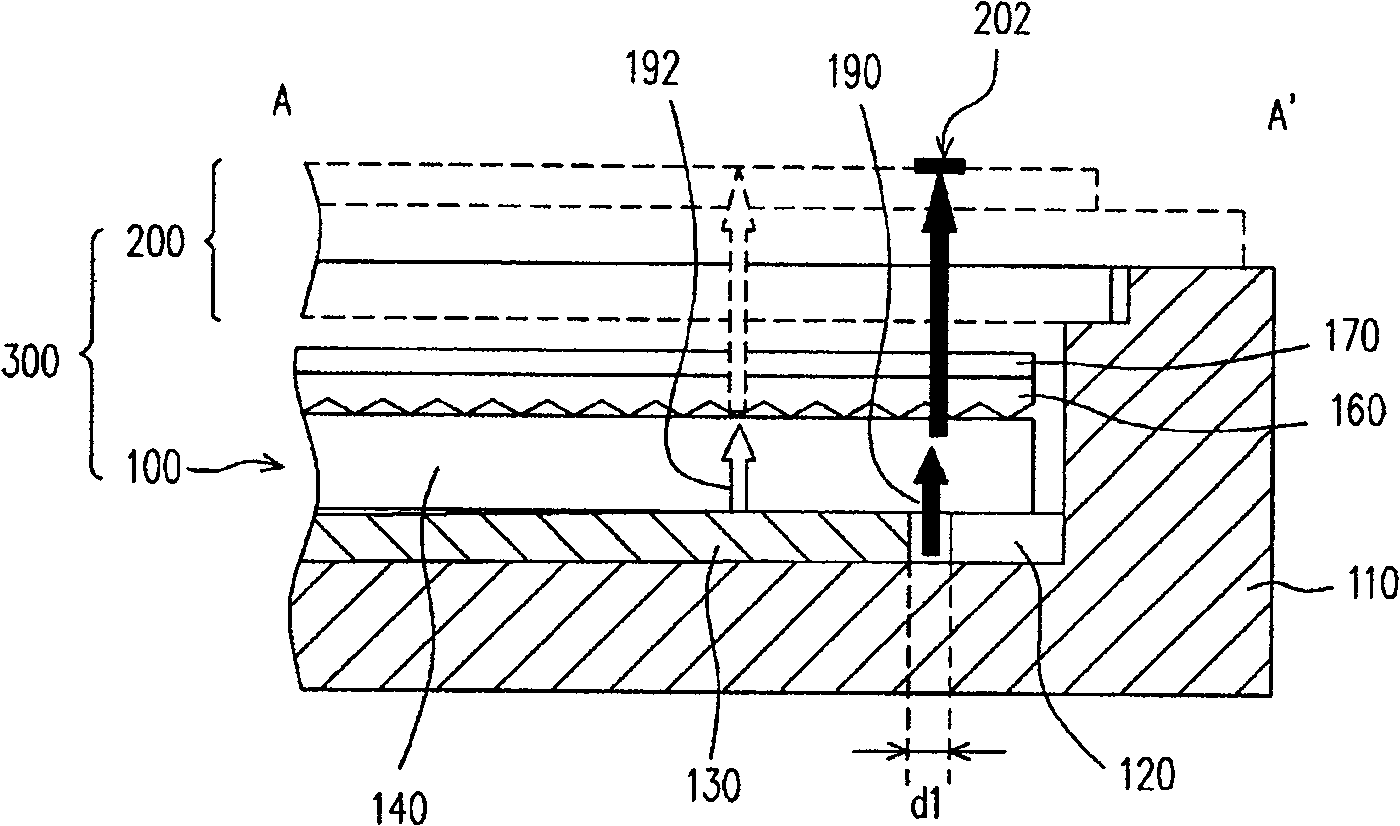
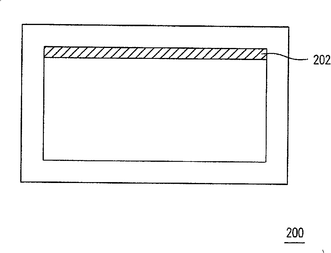
However, this method cannot ensure that there is no gap between the attachment position of the fixing tape 120 and the reflector 130 each time, that is to say, there may be a gap d1 (shown in figure 2 middle)

Method used


Image

  • Back-light module and liquid crystal display
  • Back-light module and liquid crystal display
  • Back-light module and liquid crystal display

Examples


Embodiment Construction

[0048] Figure 4 It is a perspective view of a backlight module in a preferred embodiment of the present invention. Figure 4A for Figure 4The cross-sectional schematic diagram of the backlight module along the line B-B'. Please refer to Figure 4 and Figure 4A , the backlight module 400 includes a frame 410 , a reflective tape 420 , a fixing tape 430 , a reflective plate 440 , a light guide plate 450 and at least one light source device 460 . Wherein, the side 412 of the frame 410 has a groove 414 . The reflective tape 420 is disposed in the groove 414 . The fixing tape 430 is disposed on the side 412 of the frame 410 and located on the reflective tape 420 . The reflective plate 440 is disposed in the frame 410 , wherein there is a gap d2 between the reflective plate 440 and the fixing tape 430 , and the gap d2 is located above the reflective tape 420 . The light guide plate 450 is disposed in the frame 410 and located on the reflection plate 440 and the fixing tape ...


PUM


Abstract

The invention is a backlight module, comprising frame, light reflecting adhesive tape, fixing adhesive tape, reflecting plate, light guide plate and at least a light source device, where one side of the frame has groove; the light reflecting adhesive tape is arranged in the groove; the fixing adhesive tape is arranged on the side of the frame and located on the light reflecting adhesive tape; the reflecting plate is arranged in the frame and is a gap apart from the fixing adhesive tape, and the gap is above the light reflecting adhesive tape; the light guide plate is arraged in the frame and located on the reflecting plate and the fixing adhesive tape and has at least a light incoming surface; and the light source device is arranged by the light incoming surface. And the backlight module can provide uniform plane light source.

Description

technical field [0001] The present invention relates to a backlight module and a liquid crystal display (LCD), and in particular to a backlight module capable of providing a uniform planar light source and a liquid crystal display using the backlight module. Background technique [0002] With the advancement of modern video technology, video devices are gradually trending toward light weight, large size, and thin panels. The flat panel display (FlatPanel Display), such as liquid crystal display (LCD), organic electro-luminescence display (Organic Electro-Luminescence Display, OLED) or plasma display (Plasma DisplayPanel, PDP), which is developed in conjunction with optoelectronic and semiconductor manufacturing technologies, has gradually become a The mainstream of display products. In recent years, most of the display screens on mobile phones, digital cameras, digital video cameras, notebook computers and desktop computers are based on liquid crystal display panels (LCD Pa...

Claims


Application Information

Patent Timeline
Patent Type & Authority Patents(China)
IPC IPC(8): G02F1/1335G02F1/136H01L29/786G02B5/23
Inventor 陈世昌
Owner 高智发明基金第82有限责任公司
Learn More