Driving circuit, electronic display device applying same and driving method of driving circuit

An electronic display and driving circuit technology, applied in the field of driving, can solve the problems of mismatching buffer threshold voltage, mismatching, liquid crystal display flickering, etc.

Active Publication Date: 2011-05-04
RAYDIUM SEMICON
View PDF0 Cites 2 Cited by
  • Summary
  • Abstract
  • Description
  • Claims
  • Application Information

AI Technical Summary

Problems solved by technology

However, if the frequency of the control signal is too low, close to the frequency band that can be detected by human eyes, it will cause the problem of flicker of the liquid crystal display.
[0004] In addition, when the polarity is reversed, the positive polarity and negative polarity analog driving voltages produced by the prior art will not match each other (because process factors may cause the threshold voltages of the buffers to not match each other), which may even cause mismatching. normal display

Method used


Image

  • Driving circuit, electronic display device applying same and driving method of driving circuit
  • Driving circuit, electronic display device applying same and driving method of driving circuit
  • Driving circuit, electronic display device applying same and driving method of driving circuit

Examples


Embodiment Construction

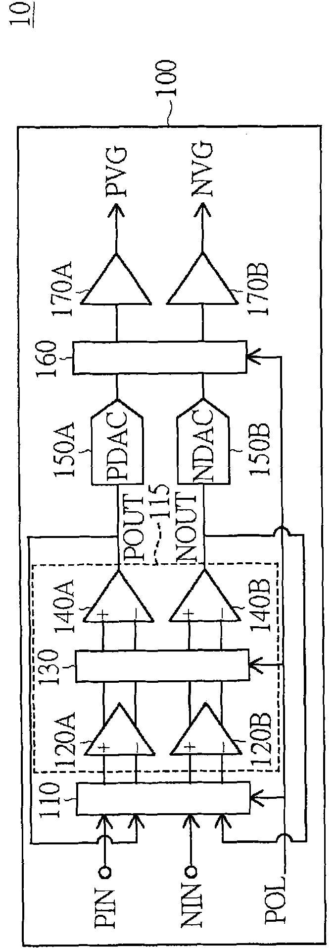
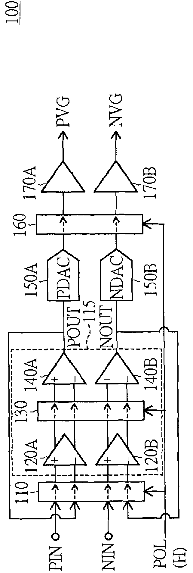
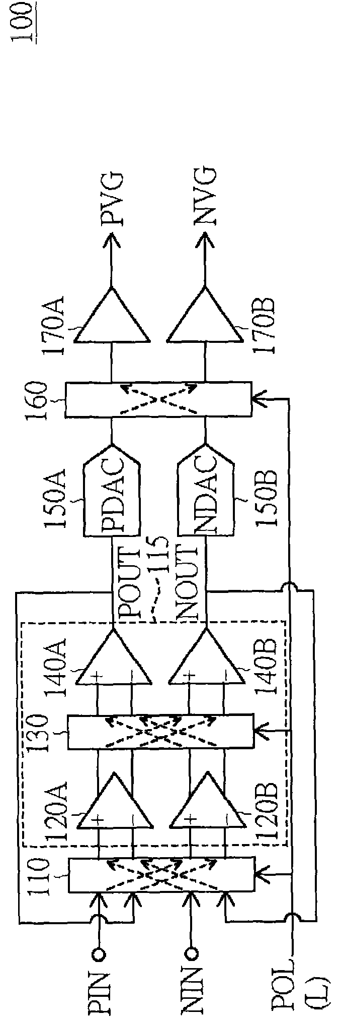
[0018] figure 1 A functional block diagram of the source driving circuit 100 according to an embodiment of the present invention is shown. Please note, figure 1 Only a part of the source driver circuit 100 is shown. Reference numeral 10 denotes a liquid crystal display, for example, a thin film transistor (TFT) liquid crystal display.

[0019] Such as figure 1 As shown, the source driver circuit 100 according to the embodiment of the present invention includes: a switching circuit 110 , a buffer 115 , a digital-to-analog converter (DAC) 150A, a DAC 150B, a switching circuit 160 , a buffer 170A, and a buffer 170B. The buffer 115 includes a first input stage (also called a gain stage) 120A, a second input stage 120B, a switching circuit 130 , a first output stage 140A, and a second output stage 140B. The buffer 170A and the buffer 170B can be regarded as channel buffers. Further, the buffers 115 , 170A and 170B can be operational amplifiers, for example.

[0020] The switc...


PUM


Abstract

The invention provides a driving circuit, an electronic display device applying the same and a driving method of the driving circuit. The driving circuit comprises a first switching circuit and a first buffer coupled to the first switching circuit. The first buffer comprises a first input stage, a second input stage, a second switching circuit, a first output stage and a second output stage, wherein the first and the second input stages are both coupled to the first switching circuit, the second switching circuit is coupled to the first and the second input stages, and the first and the second output stages are both coupled to the second switching circuit. The first switching circuit is used for alternatively coupling a first input signal and a first output signal of the first output stage to one of the first input stage or the second input stage, and alternatively coupling a second input signal and a second output signal of the second output stage to the other one of the first input stage or the second input stage. The second switching circuit is used for alternatively coupling the first input stage to one of the first output stage and the second output stage and alternatively coupling the second input stage to the other one of the first output stage and the second output stage. The driving circuit disclosed by the invention can realize the effects of simplifying controlling operation, lowering flicking frequency, and lowering or eliminating abnormal display phenomena.

Description

technical field [0001] The invention relates to a driving circuit, an electronic display device using the same and a driving method of the electronic display device. Background technique [0002] Liquid crystal display (LCD) has the advantages of low radiation and low power consumption, and has gradually become the mainstream of displays. A liquid crystal display typically includes multiple source driver circuits. The source driver circuit receives an analog driving voltage to drive the LCD panel. In the past, a separate gamma buffer generated the analog drive voltage to all source drive circuits. However, in order to reduce the cost, the gamma buffers are now integrated into the source driver circuits (that is, each source driver circuit is provided with its own gamma buffer). However, since the respective gamma buffers in each source driving circuit have different offsets, the offset among the source driving circuits will be caused, resulting in abnormal display. [00...

Claims


Application Information

Patent Timeline
Patent Type & Authority Applications(China)
IPC IPC(8): G09G3/20G09G3/36
Inventor 黄智全罗友龙吴欣晔
Owner RAYDIUM SEMICON
Why Eureka
Try Eureka