Piezoelectric vibrator

A piezoelectric vibrator and vibrating plate technology, which is applied to electrical components, impedance networks, etc., and can solve problems affecting the vibration effect of piezoelectric vibrators

Inactive Publication Date: 2013-05-22
AAC TECH PTE LTD
View PDF3 Cites 0 Cited by
  • Summary
  • Abstract
  • Description
  • Claims
  • Application Information

AI Technical Summary

Problems solved by technology

When the vibrating plate vibrates in bending, it will collide with the mass block and interfere with the vibration effect of the piezoelectric vibrator

Method used


Image

  • Piezoelectric vibrator
  • Piezoelectric vibrator

Examples


Embodiment Construction

[0012] The piezoelectric vibrator of the present invention will be described in detail below with reference to the accompanying drawings.

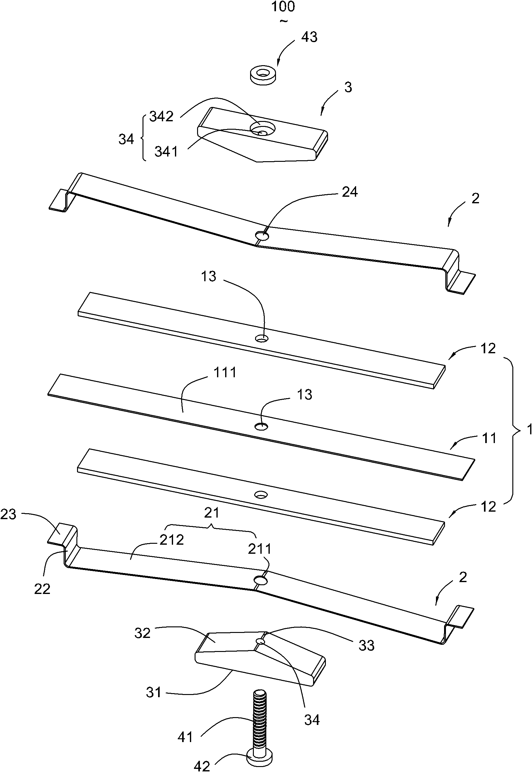
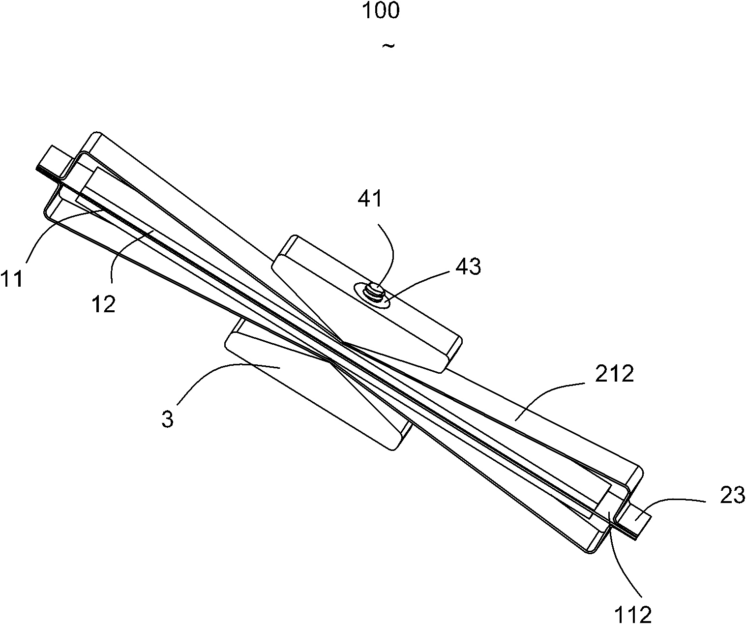
[0013] Please refer to figure 1 and figure 2 As shown, the piezoelectric vibrator 100 of the present invention is disposed in an electronic component (not shown), and the electronic component includes a mobile phone, a digital camera or other consumer electronic products.

[0014] The piezoelectric vibrator 100 includes a vibrating piece 1, a supporting piece 2 connected to the vibrating piece 1, a mass block 3 placed on the supporting piece 2, and a fixing member (not shown) passing through the vibrating piece 1, the supporting piece 2 and the mass block 3 at the same time. label).

[0015] The vibrating plate 1 is provided with a base plate 11 and ceramic plates 12 placed on both sides of the base plate 11 . The substrate 11 has a mounting surface 111 and soldering surfaces 112 extending from two ends of the mounting surface 111 . T...


PUM


Abstract

The invention discloses a piezoelectric vibrator comprising a vibrating plate and a mass block, wherein the vibrating plate is provided with a through hole passing through the vibrating plate, and the mass block is provided with a mounting hole passing through the mass block. The piezoelectric vibrator is also provided with a fixing part which simultaneously passes through the through hole and the mounting hole to stably connect the mass block with the vibrator. The piezoelectric vibrator of the invention has good stability.

Description

【Technical field】 [0001] The present invention relates to a piezoelectric vibrator. 【Background technique】 [0002] Electronic device manufacturers, especially portable electronic device manufacturers, are always improving the user experience. Traditional devices use sight and sound to provide feedback to users, such as video playback and audio playback. In some devices, motion feedback (such as active force and resistance feedback) and tactile feedback (such as vibration, thermal energy) can provide users with a more intense use experience. Specifically, the tactile effects of vibration effects and vibration haptics provide real feedback to create sensory experiences in simulated or virtual environments. For example, the explosion effect in a game console will cause a strong vibration of the user's equipment, while water droplets will cause small vibrations. The vibrations, the need for this experience, are constantly being heated. [0003] Tactile feedback is being inco...

Claims


Application Information

Patent Timeline
Patent Type & Authority Patents(China)
IPC IPC(8): H03H9/02H03H9/19
Inventor 柳林何杰
Owner AAC TECH PTE LTD
Why Eureka
Try Eureka