Piezoelectric vibrator

A piezoelectric vibrator and piezoelectric sheet technology, which is applied to electrical components, impedance networks, etc., can solve problems affecting the vibration stability of the piezoelectric vibrator, affecting the vibration effect of the piezoelectric vibrator, and falling off the quality block.

Inactive Publication Date: 2011-05-04
AAC TECH PTE LTD
View PDF3 Cites 2 Cited by
  • Summary
  • Abstract
  • Description
  • Claims
  • Application Information

AI Technical Summary

Problems solved by technology

During application, the quality block is easy to fall off from the piezoelectric sheet, which affects the vibration stability of the piezoelectric vibrator
In addition,

Method used


Image

  • Piezoelectric vibrator
  • Piezoelectric vibrator
  • Piezoelectric vibrator

Examples


Embodiment Construction

[0018] The piezoelectric vibrator of the present invention will be described in detail below with reference to the accompanying drawings.

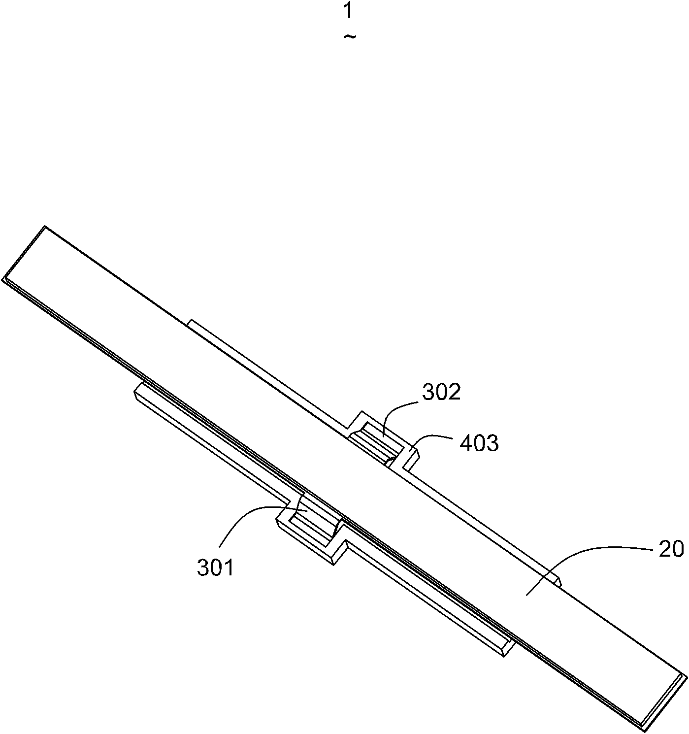
[0019] Please refer to figure 1 with figure 2 As shown, the piezoelectric vibrator 1 of the present invention is installed in an electronic component (not shown), and the electronic component includes a mobile phone, a digital camera or other consumer electronic products.

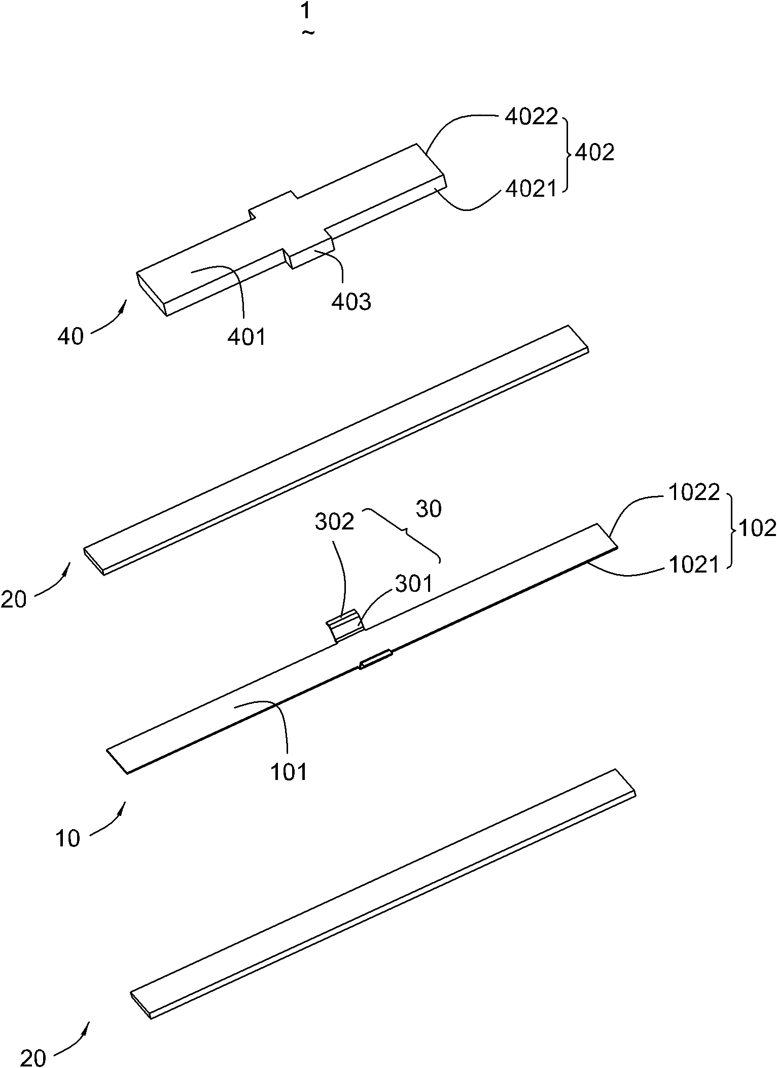
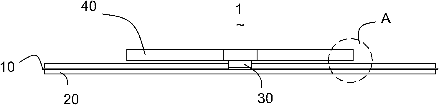
[0020] The piezoelectric vibrator 1 includes a substrate 10, piezoelectric sheets 20 placed on both sides of the substrate, a support sheet 30 extending from the substrate 10, and a mass 40 placed on the support sheet 30 and separated from the piezoelectric sheet 20 by a certain distance. .

[0021] The substrate 10 is flat and includes two opposite first surfaces 101 and a first side wall 102 connecting the two first surfaces 101, the first side wall 102 is provided with two opposite first long The sidewall 1021 and two opposite first short sidewalls 1022 .

[002...


PUM


Abstract

The invention discloses a piezoelectric vibrator. The piezoelectric vibrator comprises a substrate, piezoelectric sheets, a self-extending supporting sheet and a mass block, wherein the piezoelectric sheets are placed on the two sides of the substrate; and the mass block is placed on the supporting sheet and has a certain distance with the piezoelectric sheets. The piezoelectric vibrator has high stability.

Description

【Technical field】 [0001] The present invention relates to a piezoelectric vibrator. 【Background technique】 [0002] Electronic device manufacturers, especially portable electronic device manufacturers, are always improving the user experience. Traditional devices use sight and sound to provide feedback to users, such as video playback and audio playback. In some devices, motion feedback (such as active force and resistance feedback) and tactile feedback (such as vibration, thermal energy) can provide users with a more intense use experience. Specifically, the tactile effects of vibration effects and vibration haptics provide real feedback to create sensory experiences in simulated or virtual environments. For example, the explosion effect in a game console will cause a strong vibration of the user's equipment, while water droplets will cause small vibrations. The vibrations, the need for this experience, are constantly being heated. [0003] Tactile feedback is being inco...

Claims


Application Information

Patent Timeline
IPC IPC(8): H03H9/02
Inventor 董乐平柳林何杰
Owner AAC TECH PTE LTD
Why Eureka
Try Eureka