

Vehicle accelerator and brake device
A braking device and accelerator technology, applied in the fields of automobile accelerator and braking device and automobile braking device, can solve the problems of high energy consumption, drivers mistakenly using the accelerator as a brake, traffic safety accidents, etc., and achieve the effect of overcoming the complex structure
Inactive Publication Date: 2011-05-11
李立飞
View PDF0 Cites 0 Cited by
- Summary
- Abstract
- Description
- Claims
- Application Information
AI Technical Summary
Problems solved by technology
[0003] The purpose of the present invention is to: provide a kind of automobile accelerator and brake device, overcome the existing automobile pedal because of separate setting, easily cause the driver to have the accident of "taking the accelerator as a brake by mistake", and the occurrence of traffic safety accidents caused thereby, At the same time, it is also to overcome the defects of complex structure, high failure rate, high cost and high energy consumption of the continuously variable transmission device
Method used
View moreImage
Smart ImageViewing Examples

Examples
Embodiment Construction
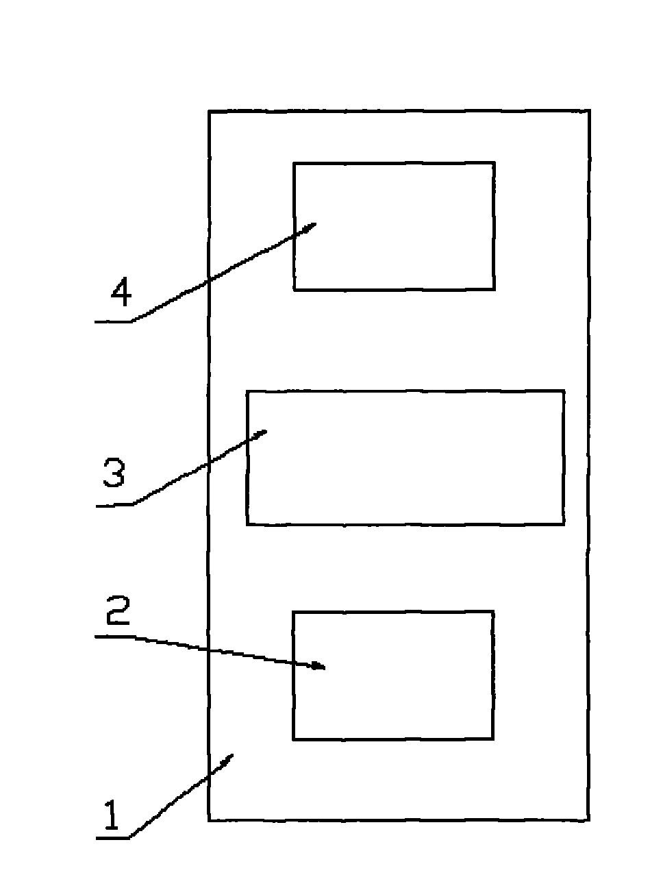
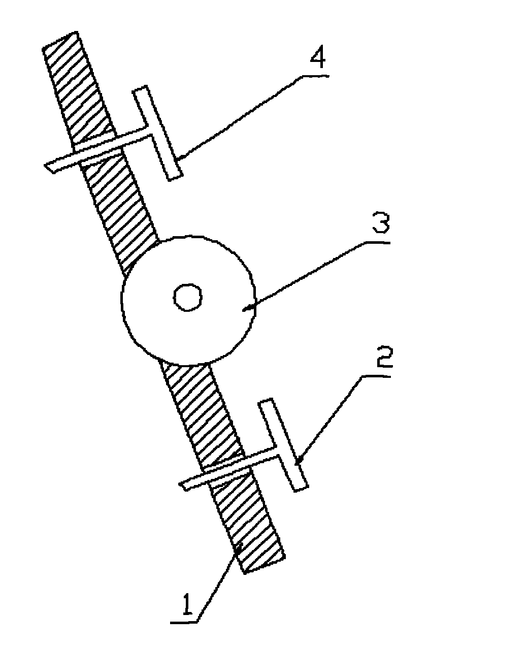
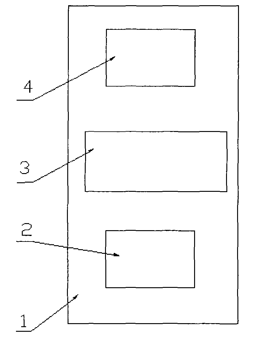
[0010] Set the accelerator pedal (2) and brake pedal (4) at appropriate positions on the upper and lower sides of a roller, install the roller (3) at an appropriate position in the middle of the isolation plate (1), and install the accelerator pedal (2) on the Install the brake pedal (4) at an appropriate position on the upper plane of the isolation plate (1) below the roller (3), and install the brake pedal (4) at an appropriate position on the upper plane of the isolation plate (1) above the roller (3). The accelerator pedal (2) and the brake pedal (4) can be installed in exchange positions on both sides of the roller (3).
Login to View More PUM
 Abstract
The invention provides a vehicle accelerator and brake device. An accelerator pedal and a brake pedal are arranged in appropriate positions on upper and lower sides of one roller wheel, the roller wheel is mounted in an appropriate position in the middle of a separation plate, the brake pedal is mounted in an appropriate position on the plane of the separation plate under the roller wheel, the brake pedal is mounted in an appropriate position on the plane of the separation plate above the roller wheel, and the accelerator brake and the brake pedal also can be mounted in changed positions on two sides of the roller wheel according to corresponding habits.
Description
technical field [0001] The invention relates to an automobile brake device, in particular to an automobile accelerator and brake device, which belongs to the technical field of motor vehicles. Background technique [0002] In order to realize the control of the car, brake pedals, clutch pedals, and accelerator pedals are installed on ordinary cars. During the driving process, the driver uses his feet to control the above three pedals according to different situations during driving. However, because one of the feet will often alternate between the accelerator pedal and the brake pedal, among many car drivers, the phenomenon of "mistakenly using the accelerator as a brake" often occurs, especially for novice drivers and drivers. Under mental stress and under other abnormal conditions, drivers are more prone to this situation. Once this situation occurs, it will not only affect normal road traffic, but also often cause significant loss of life and property; The occurrence of ...
Claims
Login to View More Application Information
Patent Timeline
 Patent Type & AuthorityApplications(China)
IPC IPC(8): B60T7/06B60K26/02
Inventor李立飞
Owner李立飞