Barrel cam shift mechanism

A technology of barrel cam and shifting mechanism, which is applied in the direction of cams, mechanical equipment, controlled components, etc.

Active Publication Date: 2011-05-11
GM GLOBAL TECH OPERATIONS LLC
View PDF4 Cites 30 Cited by
  • Summary
  • Abstract
  • Description
  • Claims
  • Application Information

AI Technical Summary

Problems solved by technology

Likewise, the actuation control system will typica...

Method used


Image

  • Barrel cam shift mechanism
  • Barrel cam shift mechanism
  • Barrel cam shift mechanism

Examples


Embodiment Construction

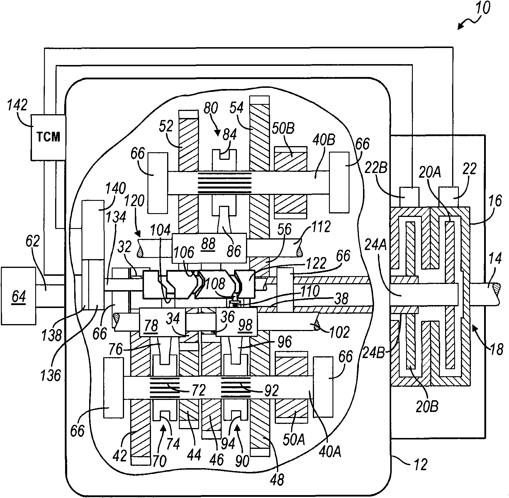
[0057] The following description is merely exemplary in nature and is not intended to limit the disclosure, application, or use. figure 1 , it should be understood that some parts have been rotated out of their actual positions and into the plane of the view for clarity.

[0058] refer to figure 1 , shows a dual clutch transmission containing a barrel cam shifting mechanism according to the invention, which is generally indicated by reference numeral 10 . The dual clutch transmission 10 includes a housing 12 having a plurality of bores, openings, flanges, etc. that receive, locate and retain components of the transmission 10 . The input shaft 14 is coupled to and driven by a prime mover (not shown), such as a gasoline engine, diesel engine, hybrid or electric power plant. The input shaft 14 is coupled to an input or housing 16 of a dual clutch assembly 18 . The dual clutch assembly 18 includes a pair of input clutches, a first input clutch 20A and a second input clutch 20B ...


PUM


Abstract

A shift mechanism for a dual clutch transmission employs a rotating barrel cam having at least three tracks which are engaged by and translate at least three associated cam followers. The cam followers extend from shift fork bodies which slide on rails and include shift forks which bi-directionally translate at least three synchronizer clutches which engage at least five forward gears or speeds and reverse. A single electric motor and gear train drive the barrel cam.

Description

technical field [0001] The present disclosure relates to barrel cam shifters for transmissions, and more particularly to single motor driven barrel cam shifters for actuating shift forks in dual clutch transmissions. Background technique [0002] The statements in this section merely provide background information related to the present disclosure and may not constitute prior art. [0003] The shifting mechanism of the motor vehicle transmission has various forms. In a typical manual transmission, an operator-guided shift lever acts on multiple parallel fork rails that include shift forks that engage and translate clutches that achieve the desired gear with synchronizer. In an automatic transmission, hydraulically operated clutches and brakes controlled by a plurality of logic and control valves engage, disengage, and brake elements of a planetary gear assembly. In a newer transmission type, the dual clutch transmission (DTC), multiple synchronizer clutches on both laysha...

Claims


Application Information

Patent Timeline
IPC IPC(8): F16H59/04F16H63/32F16H25/12F16H53/08
CPCF16H3/006F16H61/32F16H61/688F16H63/18Y10T74/20177Y10T74/19279
Inventor V·A·尼拉肯坦B·M·奥尔森J·B·布拉德利A·S·格鲁瓦尔
Owner GM GLOBAL TECH OPERATIONS LLC
Why Eureka
Try Eureka