Timing valve
A valve and timing technology, applied in the direction of sliding valve, valve details, valve device, etc., can solve the problems of safety, hidden danger, pet collision and damage, etc., to achieve the effect of safe use and simple structure
- Summary
- Abstract
- Description
- Claims
- Application Information
AI Technical Summary
Problems solved by technology
Method used
Image
Examples
Embodiment Construction
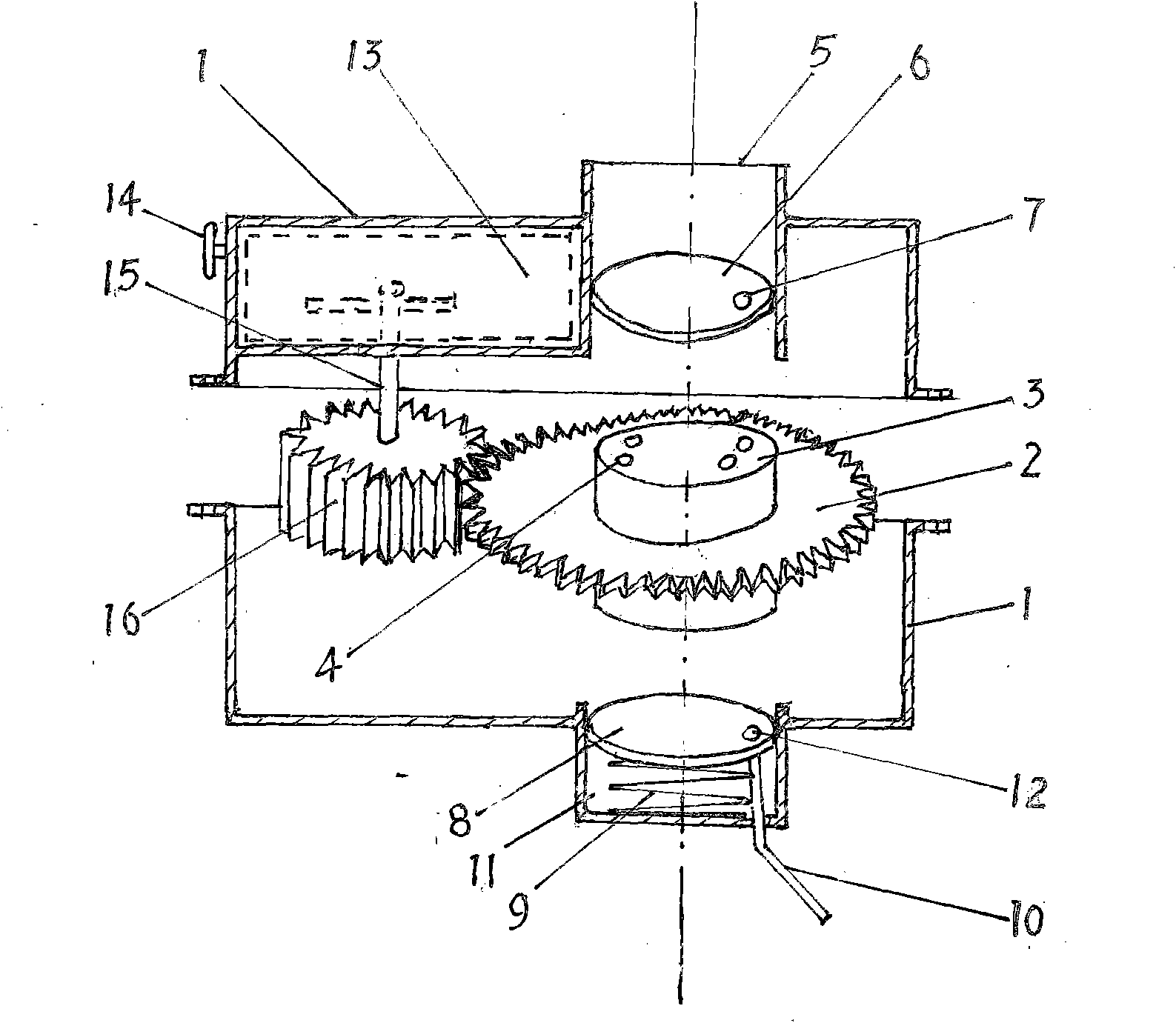
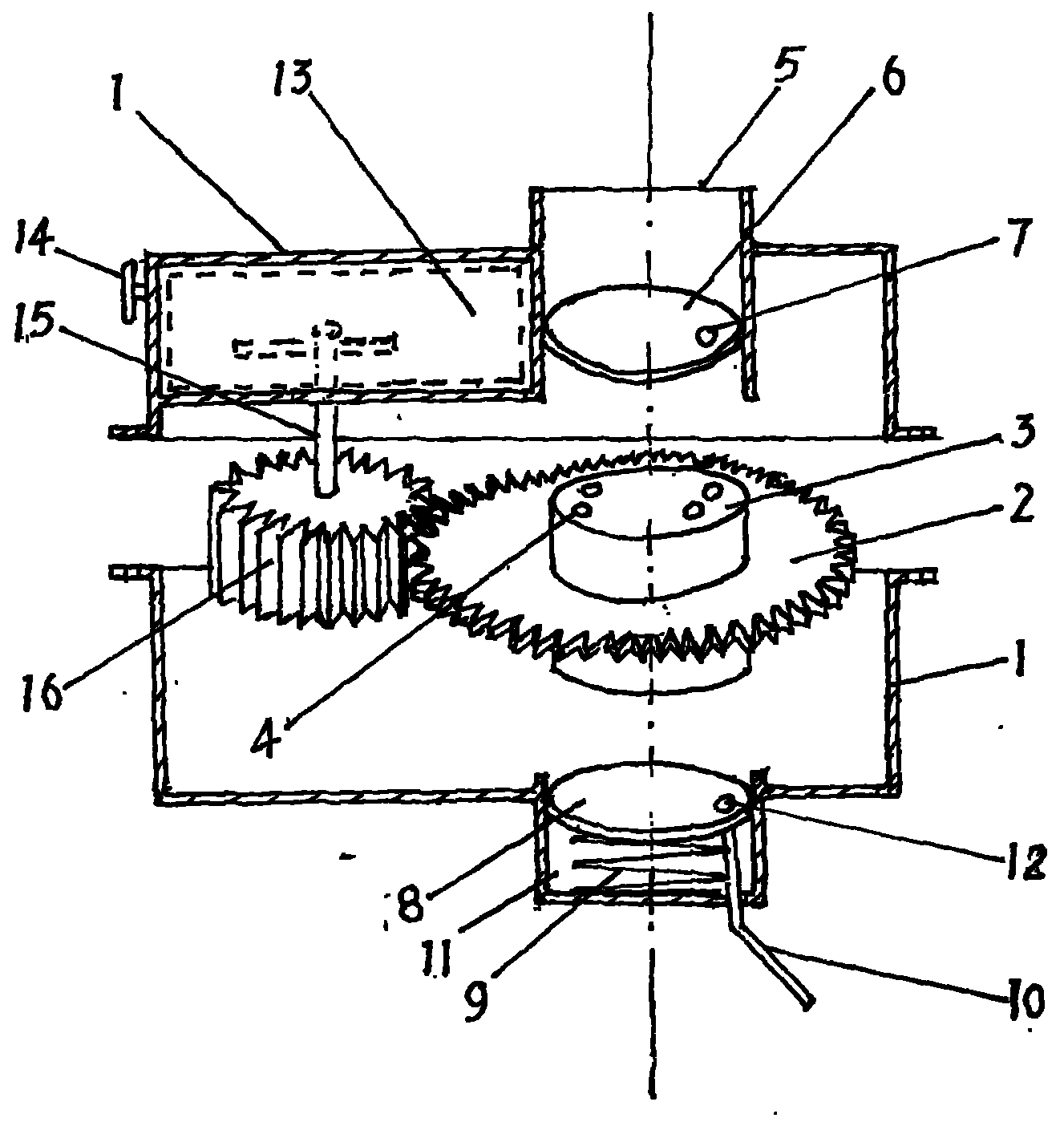
[0009] In the figure, the valve casing 1 is made into a groove shape, divided into upper and lower jaws, and the flange of the jaws is connected with bolts to form an internal cavity. The valve core 3 is made into a cylindrical shape and installed in the center hole of the valve core gear 2, close to the outer circle edge. Hole 4, the mesh number of the hole is determined by the number of times of feeding, the aperture is determined by the nature of the circulating medium, and the distance between the holes determines the interval of feeding, that is to say, opening one hole is for opening a meal timing, opening two The hole is for the timing of the second meal. Water circulates in the hole, and the aperture can be smaller. If the pellet feed is circulated, the aperture will be much larger. The longer the distance between the holes, the longer the timer rotates at a fixed speed. The longer the interval between meals, these bars are pre-set when the valve is manufactured. The b...
PUM
 Abstract
Description
Claims
Application Information
 - R&D
- Intellectual Property
- Life Sciences
- Materials
- Tech Scout
- Unparalleled Data Quality
- Higher Quality Content
- 60% Fewer Hallucinations
Browse by: Latest US Patents, China's latest patents, Technical Efficacy Thesaurus, Application Domain, Technology Topic, Popular Technical Reports.
© 2025 PatSnap. All rights reserved.Legal|Privacy policy|Modern Slavery Act Transparency Statement|Sitemap|About US| Contact US: help@patsnap.com


