
Building formwork connecting frame for civil engineering

A technology for building formwork and civil engineering, applied in the direction of formwork/formwork/work frame, construction, building structure, etc., can solve the problems of low construction efficiency, difficult on-site management, waste of materials, etc., and achieve energy saving and convenient driving. Effect

Inactive Publication Date: 2020-04-21
NORTH CHINA UNIV OF WATER RESOURCES & ELECTRIC POWER
View PDF14 Cites 1 Cited by
  • Summary
  • Abstract
  • Description
  • Claims
  • Application Information

AI Technical Summary

Problems solved by technology

[0002] The building formwork is a temporary support structure. The building formwork can maintain its correct position and bear the self-weight of the building formwork and the external load acting on it. The formwork project can ensure the quality of concrete engineering and construction safety, speed up the construction progress and To reduce the cost of the project, the building formwork will use the connecting frame when connecting. The connecting frame in the traditional craft is a combination of wooden formwork, wooden squares and steel pipe brackets. This structure requires full clips, assembly and construction. The workload is heavy, the operation is complicated, the construction efficiency is low, and a lot of materials will be wasted, among which the waste of wood is the most serious, and the on-site management is difficult, and the fire hazard is great, so it needs to be improved urgently

Method used


Image

  • Building formwork connecting frame for civil engineering
  • Building formwork connecting frame for civil engineering
  • Building formwork connecting frame for civil engineering

Examples


Embodiment Construction

[0025] The following will clearly and completely describe the technical solutions in the embodiments of the present invention with reference to the accompanying drawings in the embodiments of the present invention. Obviously, the described embodiments are only some, not all, embodiments of the present invention. Based on the embodiments of the present invention, all other embodiments obtained by persons of ordinary skill in the art without making creative efforts belong to the protection scope of the present invention.

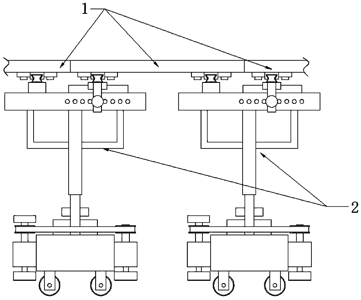
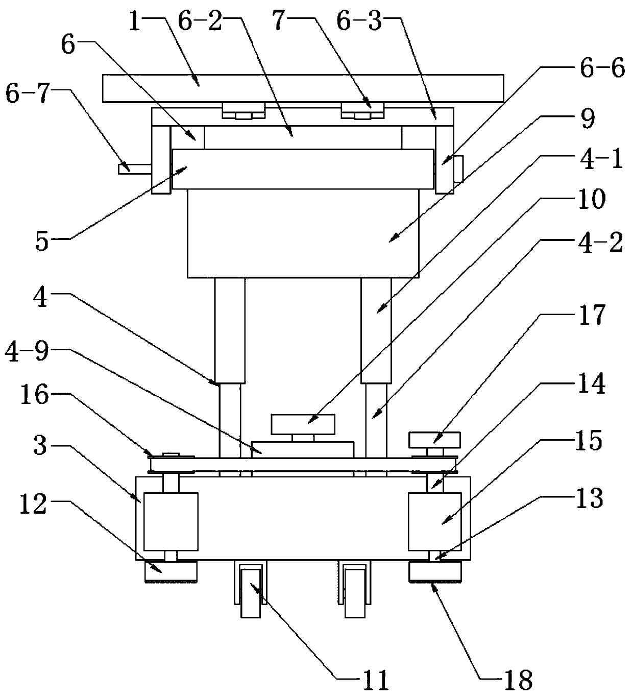
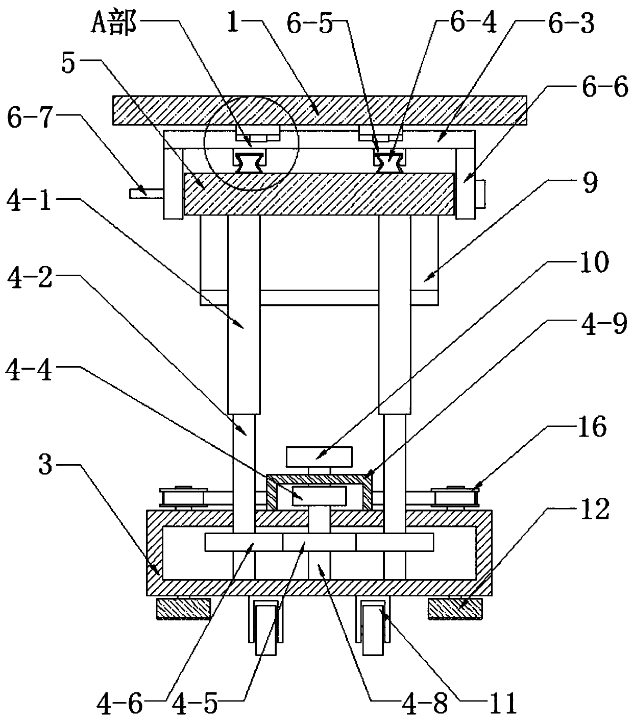
[0026] Such as Figure 1-Figure 7 As shown, this specific embodiment adopts the following technical scheme: it includes a building formwork 1 and a connecting frame 2, and the connecting frame 2 is composed of a base 3, a supporting mechanism 4, a fixing plate 5 and an adjusting mechanism 6, the base 3 is a hollow structure, and the base The upper side of 3 is suspended with a fixed plate 5, and the lower surfaces of the front and rear sides of the fixed plate...


PUM


Abstract

The invention discloses a building formwork connecting frame for civil engineering, and relates to the technical field of civil engineering equipment. A fixing plate is suspended on the upper side ofa base, wherein the lower surfaces of the front side and the rear side of the fixing plate are fixedly connected with the upper end of a first internal threaded pipe in a supporting mechanism; an adjusting mechanism is arranged on the upper surface of the fixing plate; limiting plates are fixed to the front side and the rear side of a first sliding block on the front side and the rear side of theupper side of the adjusting mechanism; the limiting plates are fixed to the lower surface of a building formwork; the outer side of the building formwork is sleeved with graphite rings; and the outeredges of every two adjacent graphite rings are arranged in a contact mode. The building formwork is fixed to the first sliding block on the adjusting mechanism, the position of the building formwork can be adjusted through the adjusting mechanism, the adjusting mechanism is fixed to the fixing plate, the fixing plate is fixed to the first internal threaded pipe in the supporting mechanism, the height of the building formwork is adjusted through the supporting mechanism, and then the building formwork connecting frame is suitable for buildings with different storey heights. The building formwork connecting frame has the advantages of being reasonable in arrangement, low in manufacturing cost and the like.

Description

technical field [0001] The invention relates to the technical field of civil engineering equipment, in particular to a building formwork connecting frame for civil engineering. Background technique [0002] The building formwork is a temporary support structure. The building formwork can maintain its correct position and bear the self-weight of the building formwork and the external load acting on it. The formwork project can ensure the quality of concrete engineering and construction safety, speed up the construction progress and To reduce the cost of the project, the building formwork will use the connecting frame when connecting. The connecting frame in the traditional craft is a combination of wooden formwork, wooden squares and steel pipe brackets. This structure requires full clips, assembly and construction. The workload is heavy, the operation is complicated, the construction efficiency is low, and a lot of materials will be wasted, among which the waste of wood is t...

Claims


Application Information

Patent Timeline
IPC IPC(8): E04G11/48E04G25/06
CPCE04G11/48E04G25/06E04G2025/003E04G2025/006
Inventor 朱学超陈记豪曾桂香
Owner NORTH CHINA UNIV OF WATER RESOURCES & ELECTRIC POWER
Learn More