Precision pressure reducing valve structure
A pressure reducing valve, precision technology, applied in the direction of safety valve, balance valve, valve device, etc., can solve the problems of poor air tightness, unfavorable alignment and rotation, etc., and achieve good air tightness effect
- Summary
- Abstract
- Description
- Claims
- Application Information
AI Technical Summary
Problems solved by technology
Method used
Image

Examples
Embodiment Construction
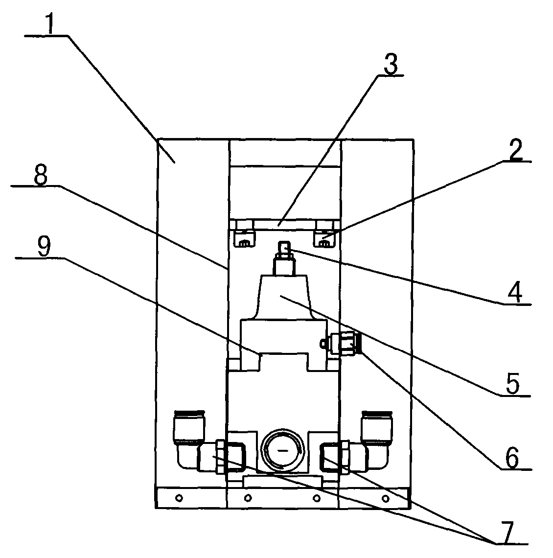
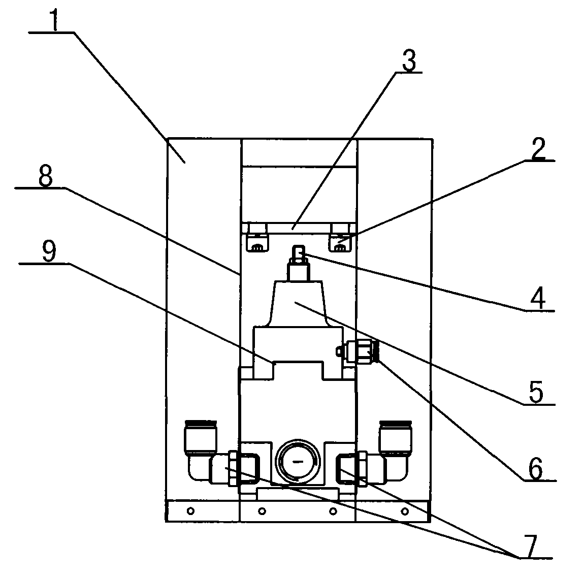
[0011] Such as figure 1 As shown, the structure of the precision pressure reducing valve of the present invention includes an outer casing 1, a pneumatic valve 5 and a valve body 8. A valve body 8 is arranged inside the outer casing 1, and an air pump 7 is arranged at both ends of the valve body 8. Each air pump 7 extends into the bottom side of the inner core of the valve body 8 and is connected with the lower sealing plate in the valve, and the upper sealing plate 3 is installed on the top side of the outer shell 1 through several tightening bolts 2; the middle part of the valve body 8 is provided with an adjusting plate 9 and its two sides are close to the two side walls of the valve body 8, and the adjustment bolt 6 is set on the adjustment plate 9, the pneumatic valve 5 is arranged on the upper part of the adjustment plate 9 and a sliding knob 4 is movably connected to the top of the adjustment plate 9, and the sliding knob 4 A certain cavity is set between the upper seal...
PUM
 Abstract
Description
Claims
Application Information
 - Generate Ideas
- Intellectual Property
- Life Sciences
- Materials
- Tech Scout
- Unparalleled Data Quality
- Higher Quality Content
- 60% Fewer Hallucinations
Browse by: Latest US Patents, China's latest patents, Technical Efficacy Thesaurus, Application Domain, Technology Topic, Popular Technical Reports.
© 2025 PatSnap. All rights reserved.Legal|Privacy policy|Modern Slavery Act Transparency Statement|Sitemap|About US| Contact US: help@patsnap.com