Inner rotor type motor

A rotor type and motor technology, applied in the direction of magnetic circuit rotating parts, magnetic circuit shape/style/structure, casing/cover/support, etc., can solve the complicated assembly components and steps, increase the difficulty of positioning, and affect the motor. Assembly efficiency and other issues

Active Publication Date: 2011-05-11
SUNONWEALTH ELECTRIC MACHINE IND
View PDF2 Cites 4 Cited by
  • Summary
  • Abstract
  • Description
  • Claims
  • Application Information

AI Technical Summary

Problems solved by technology

[0006] However, since the barrier piece 96 is an independent component, it needs to be positioned on the outer peripheral surface of the rotating shaft 931 by tight fit or other combination methods before the rotating shaft 931 is assembled on the bearing 95, resulting in the existing inner rotor type The assembly components and steps of the motor 9 are too complicated; moreover, in order to ensure that the barrier sheet 96 must be attached to the bottom surface of the permanent magnet 94 or the top surface of the bearing 95, so as to prevent the powder impurities falling from the permanent magnet 94 from entering the bearing 95, it increases the difficulty of positioning the barrier piece 96 assembled on the rotating shaft 931, which in turn affects the overall assembly efficiency of the motor

Method used


Image

  • Inner rotor type motor
  • Inner rotor type motor
  • Inner rotor type motor

Examples


Embodiment Construction

[0035] In order to make the above-mentioned and other objects, features and advantages of the present invention more comprehensible, the preferred embodiments of the present invention are specifically cited below, together with the accompanying drawings, as follows:

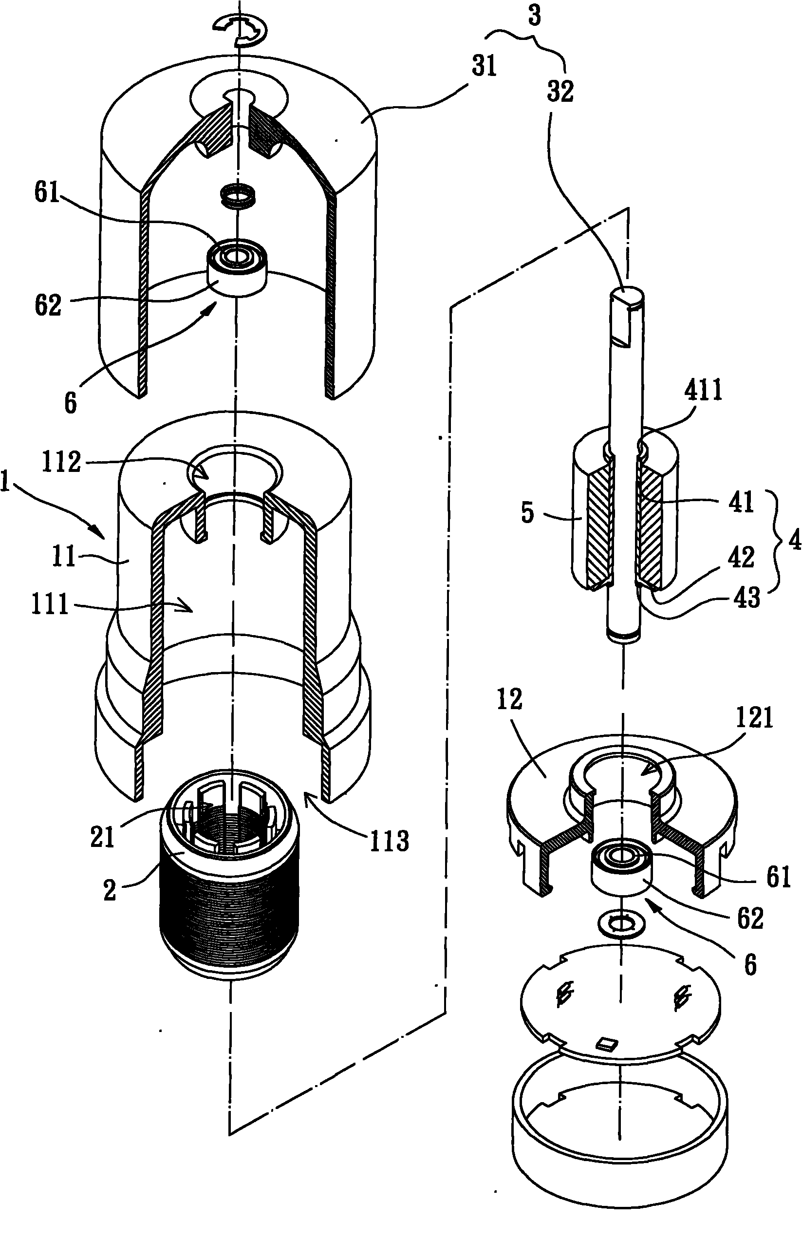
[0036] Please refer to image 3 and 4 As shown, the inner rotor motor of the first embodiment of the present invention includes a shell 1 , a stator 2 , a rotor 3 , a bearing seat 4 , a permanent magnet 5 and two bearings 6 .

[0037] The case 1 of this embodiment is composed of a body 11 and a base 12. The body 11 has an accommodating space 111, a first through hole 112 and an assembly 113. The accommodating space 111 is formed inside the body 11. The stator 2 , the bearing seat 4 , the permanent magnet 5 and the two bearings 6 are all accommodated in the accommodating space 111 . The first through hole 112 and the assembly 113 are respectively disposed on the top and the bottom of the body 11 , and communicat...


PUM


Abstract

The invention provides an inner rotor type motor which comprises a shell, a stator, a rotor, a bearing seat and a permanent magnet, wherein the shell is provided with an accommodating space, the stator is arranged in the accommodating space, the rotor is provided with a rotating shaft, the rotor enables the rotating shaft to be rotatably accommodated in a through hole of the stator by using a bearing, the bearing seat is provided with a seat body and a blocking ring lip, the seat body is arranged on the outer peripheral surface of the rotating shaft, the blocking ring lip radially extends to form an end part of the seat body, and the permanent magnet is arranged on the peripheral surface of the seat body. The blocking ring lip is formed between the permanent magnet and the bearing, thus the bearing seat ensures that impurities can not fall into and accumulate in the bearing or a jointing beam between the bearing and the rotating shaft, further maintains the smoothness of the rotation of the rotating shaft, and prolongs the service life of the rotating shaft.

Description

technical field [0001] The invention relates to an inner rotor motor, in particular to an inner rotor motor which prevents powder impurities from entering the inside of the bearing. Background technique [0002] Existing inner rotor motor 8, please refer to figure 1 As shown, it generally includes a casing 81 , a stator 82 , a rotor 83 and a permanent magnet 84 . The housing base 81 has an accommodating space 810 , and the stator 82 is disposed in the accommodating space 810 . The stator 82 has a through hole 821 , and the through hole 821 axially passes through the top end surface and the bottom end surface of the stator 82 . The rotor 83 is provided with a rotating shaft 831 and a bearing seat 832 , the rotating shaft 831 is rotatably positioned in the through hole 821 by means of two bearings 85 , and the bearing seat 832 is sheathed on the outer peripheral surface of the rotating shaft 831 . The permanent magnet 84 is sleeved on the outer peripheral surface of the rot...

Claims


Application Information

Patent Timeline
Patent Type & Authority Applications(China)
IPC IPC(8): H02K1/27H02K5/00H02K5/16
Inventor 洪银树尹佐国刘嘉峻
Owner SUNONWEALTH ELECTRIC MACHINE IND
Why Eureka
Try Eureka