Actuating device

A technology of operating device and accommodating sleeve, applied in the field of operating device of valve, can solve the problem of limited possibility of error compensation and achieve the effect of reliable support

Inactive Publication Date: 2011-05-11
HYDAC ELECTRONICS GMBH
View PDF2 Cites 1 Cited by
  • Summary
  • Abstract
  • Description
  • Claims
  • Application Information

AI Technical Summary

Problems solved by technology

However, due to the defined clamping position of the pole tube between the p

Method used


Image

  • Actuating device
  • Actuating device
  • Actuating device

Examples


Embodiment Construction

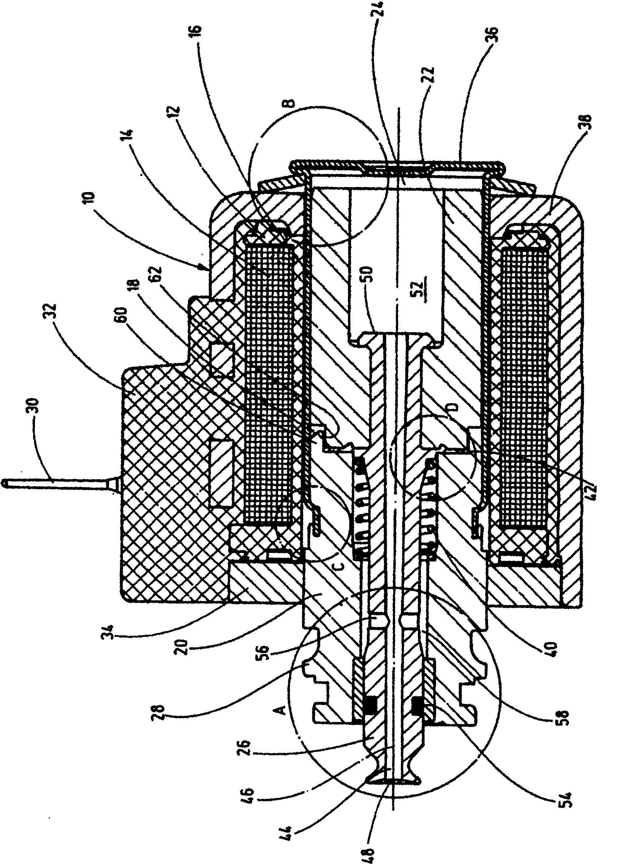
[0024] exist figure 1 The actuating device shown in longitudinal section in FIG. 2 , also referred to in the art as an “actuating and switching magnet”, has a housing indicated overall at 10 in which a coil body 12 with a coil winding 14 is arranged. The coil body 12 at least partially surrounds a pole tube 16 , which is essentially electromagnetically decoupled from the pole core 20 by means of a separation point 18 in the form of a recess. However, such solutions (not shown) are also known in the prior art, in which the corresponding separation points are formed by welded seams or the like. A magnetic armature 22 is guided longitudinally displaceably along the pole tube 16 in the armature chamber 24 , which interacts at its one free front end with a rod-shaped actuating part 26 for actuating conventional designs. Fluid valves (not shown) in the form of, in particular, not shown pneumatic valves. For connecting the valve, the pole core 20 is provided with a connecting flang...


PUM


Abstract

The invention relates to an actuating device, particularly for actuating valves that can be connected externally, comprising a housing (10) and a coil body (12) arranged therein and having a coil winding (14), which encloses a pole tube (16) at least partially, having a pole core (20) connected at the free end thereof, further comprising an armature (22) that is guided in a longitudinally displaceable manner at least in the pole tube (16) within an armature chamber (24) and interacts with an actuating part (26) for actuating the respective valve part, wherein the pole tube (16) is designed in the form of a receiving sleeve for the armature (22), said sleeve being fixed to a fixed bearing point (124), wherein on a floating bearing point (116) for the receiving sleeve restoring means (112) engage thereon, effecting a force on the receiving sleeve that is directed away from the fixed bearing point (124).

Description

technical field [0001] The invention relates to an actuating device, in particular for actuating an externally connectable valve, having a housing and a coil body arranged in the housing with a coil winding, the coil body at least partially enclosing a pole tube, A pole core is connected to the free end of the pole tube, the actuating device having a longitudinally displaceable magnetic armature guided at least in the pole tube within the armature, which interacts with an actuating element for actuating the corresponding valve element, In this case, the pole tube is formed in the form of a receiving sleeve for the magnetic armature, which is fixed at a fixed bearing point. Background technique [0002] Such an actuating device is known from DE 10 2004 051 332 A1. In this known solution, the pole tube is provided with a surrounding edge on its free end protruding from the actuating device housing, on which edge the magnetic armature can be supported in its end-side displacem...

Claims


Application Information

Patent Timeline
IPC IPC(8): H01F7/126H01F7/08F16K31/06H01F7/16
CPCH01F7/081H01F7/088H01F7/127H01F7/1607H01F2007/163
Inventor M·比尔F·劳尔M·米勒
Owner HYDAC ELECTRONICS GMBH
Why Eureka
Try Eureka