Joint fastening member and fastening connecting member

A technology for fastening connectors and fasteners, applied in the direction of connecting components, threaded fasteners, locking fasteners, etc. Connecting parts are loosened and other problems to prevent loosening

Inactive Publication Date: 2011-05-18
刘玉柱
View PDF6 Cites 2 Cited by
  • Summary
  • Abstract
  • Description
  • Claims
  • Application Information

AI Technical Summary

Problems solved by technology

[0002] Fastening connectors are widely used in various fields such as life and electricity, and play an important role. Most of the fastening connectors on the market are fixed by simple threads, which can play a role to a certain extent, but at the same time There are also some disadvantages; for example: the user is unskilled. When fixing, if the fastening connector is not tightened, it will affect the fastening effect of the fastening connector. If the tightening is too tight, the fastening connector will be damaged, and the fastening connector It can also loosen during prolonged use

Method used


Image

  • Joint fastening member and fastening connecting member
  • Joint fastening member and fastening connecting member
  • Joint fastening member and fastening connecting member

Examples


Embodiment 1

[0030] (Embodiment 1, joint fastener)

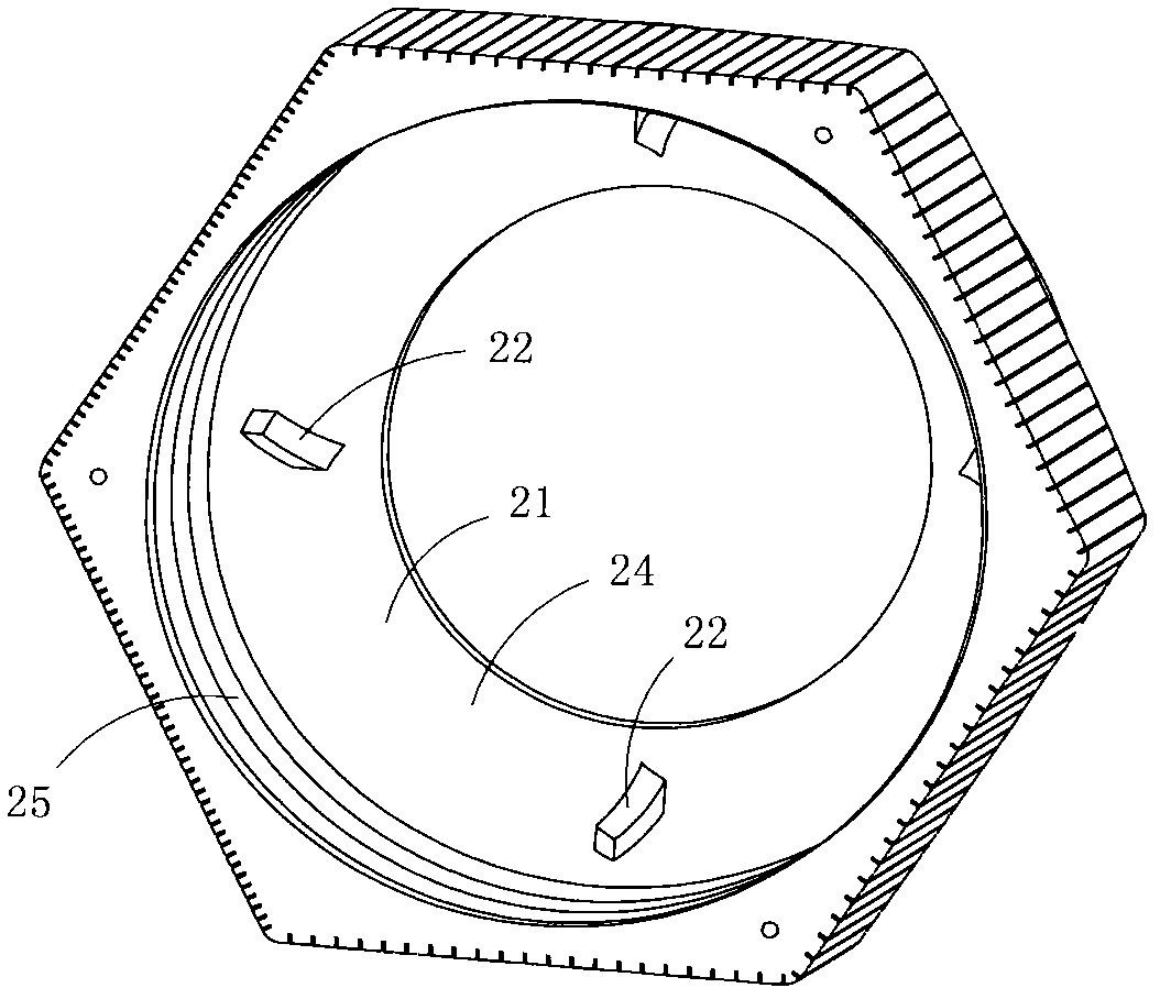
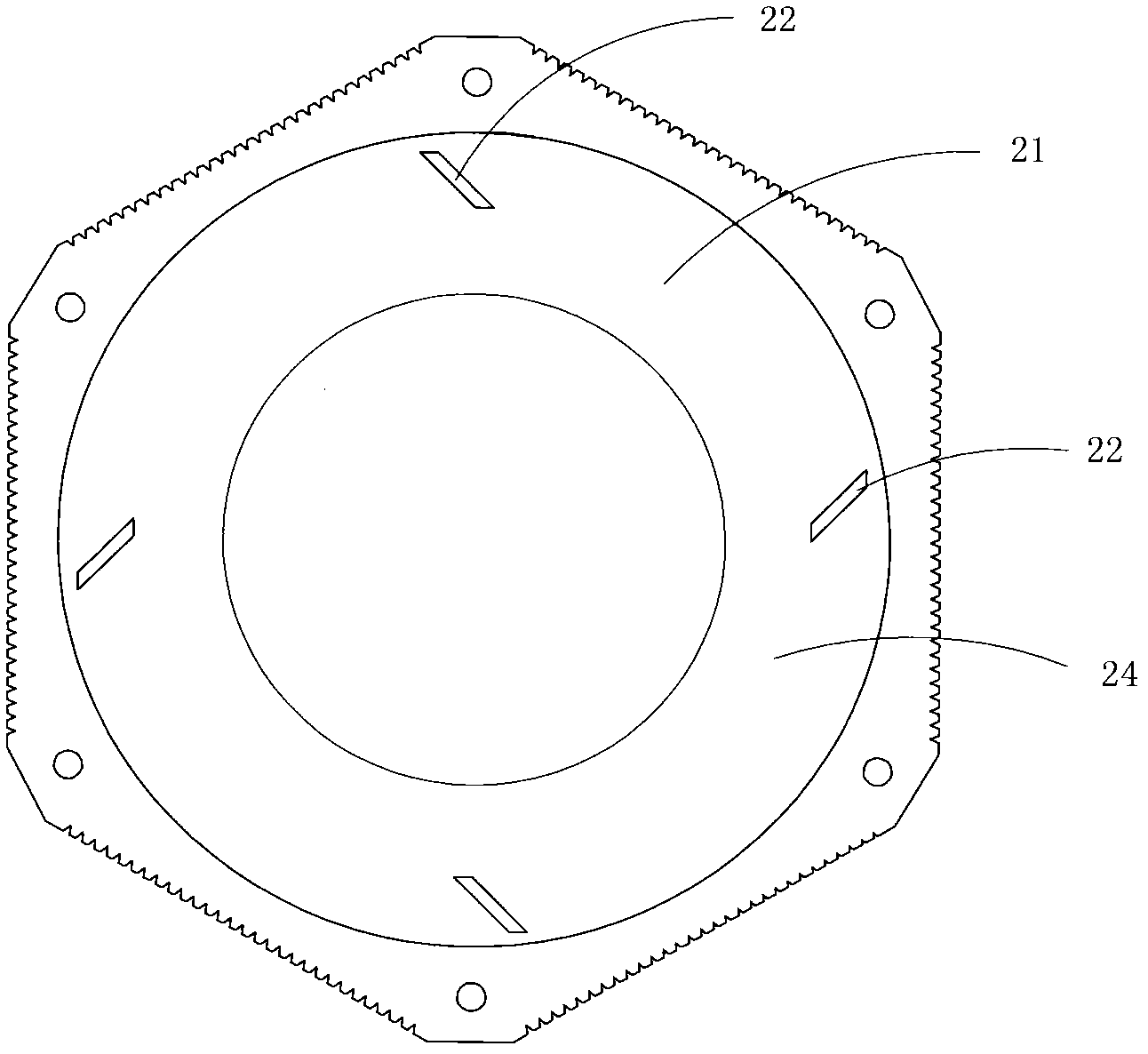
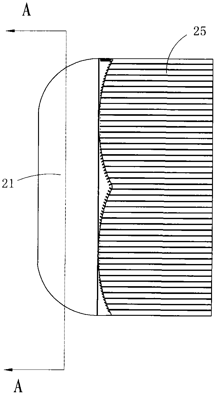
[0031] Figure 1 to Figure 4 An embodiment of the joint fastener of the present invention is shown, wherein, figure 1 It is a three-dimensional structural schematic diagram of the first structure of the joint fastener in the present invention; figure 2 yes figure 1 An elevational view of the joint fastener shown; image 3 yes figure 1 A side view of the joint fastener shown; Figure 4 yes image 3 Sectional view along line A-A.

[0032] This embodiment is a joint fastener, see Figure 1 to Figure 4 Its basic shape is tubular, including a fastening area 25 with an internal thread and a crimping area 21 with a crimping surface 24 inside. The crimping surface 24 is provided with several raised anti-skid teeth 22 . The anti-slip teeth 22 are evenly distributed on the crimping surface 24 and arranged equidistantly around the central axis of the joint fastener 1 . See figure 2 As shown, the extension direction of each anti-slip too...

Embodiment 2

[0034] (Embodiment 2, Joint Fastener)

[0035] Figure 5 It is a longitudinal sectional view of the second structure of the joint fastener in the present invention, showing the second specific embodiment of the joint fastener in the present invention.

[0036] This embodiment is basically the same as Embodiment 1, the difference is: see Figure 5 , the shape of the longitudinal section of each of the anti-skid teeth 22 is a right-angled trapezoid.

Embodiment 3

[0037] (Embodiment 3, joint fastener)

[0038] Figure 6 It is a longitudinal sectional view of the third structure of the joint fastener in the present invention, showing the third embodiment of the joint fastener in the present invention.

[0039] This embodiment is basically the same as Embodiment 1, the difference is: see Figure 6 , the shape of the longitudinal section of each anti-skid tooth 22 is an isosceles trapezoid.


PUM


Abstract

The invention discloses a joint fastening member and a fastening connecting member. The joint fastening member is basically shaped as a tube and comprises a fastening region with an internal thread and a compression joint region internally provided with a compression joint surface, and a plurality of protruding anti-skidding teeth are arranged on the compression joint surface. The fastening connecting member comprises a plastic joint body and a plastic joint fastening member, the joint body is basically shaped as a tube and comprises a connecting region with an external thread and a sealing region with a plurality of sealing teeth, the sealing teeth are arranged annularly; and the joint fastening member is basically shaped as a tube and comprises a fastening region with an internal thread and a compression joint region internally provided with a compression joint surface, a plurality of protruding anti-skidding teeth are arranged on the compression joint surface of the joint fastening member, and the anti-skidding teeth support against the sealing teeth of the joint body. The invention has the advantage of effectively preventing the fastening connecting member from loosening and has a prompt function.

Description

technical field [0001] The invention belongs to the technical field of connector structure design, and in particular relates to a joint fastener and a fastening connector made of the joint fastener. Background technique [0002] Fastening connectors are widely used in various fields such as life and electric power and play an important role. Most of the fastening connectors on the market are fixed by simple threads, which can play a role to a certain extent, but at the same time There are also some disadvantages; for example: the user is unskilled. When fixing, if the fastening connector is not tightened, it will affect the fastening effect of the fastening connector. If the tightening is too tight, the fastening connector will be damaged, and the fastening connector will Looseness can also occur during prolonged use. Contents of the invention [0003] The object of the present invention is to provide a joint fastener with anti-loosening function. [0004] Another object...

Claims


Application Information

Patent Timeline
IPC IPC(8): F16B37/00F16B39/28F16B41/00
Inventor 刘玉柱
Owner 刘玉柱
Why Eureka
Try Eureka