
Rotary limiting device for vehicle

A limit device and rotary technology, applied in measuring devices, vehicle testing, instruments, etc., can solve problems such as motor vehicle instability, achieve simple and convenient operation, wide application range, and easy popularization and use

Inactive Publication Date: 2011-05-18
ZHEJIANG UNIV
View PDF5 Cites 5 Cited by
  • Summary
  • Abstract
  • Description
  • Claims
  • Application Information

AI Technical Summary

Problems solved by technology

[0004] At present, some motor vehicles have no front brake or the front brake force is very small, so the motor vehicle is unstable during the detection, and may move forward with the rolling of the roller, so a vehicle limit device is needed. Ability to secure a motor vehicle

Method used


Image

  • Rotary limiting device for vehicle
  • Rotary limiting device for vehicle
  • Rotary limiting device for vehicle

Examples


Embodiment Construction

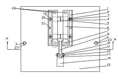
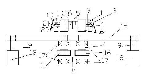
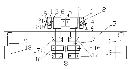
[0015] The rotary vehicle position limiting device of the present invention is mainly composed of a working plate 15, a position limiting mechanism, a transmission mechanism and two cylinders 18 and the like.

[0016] Such as figure 1 and figure 2 As shown, the limit mechanism is used to provide a limit function for the wheels of the detected vehicle. The limit mechanism includes two left and right fixed limit plates 6 spaced apart from each other, so that the limit mechanism is divided into left and right parts. More than two first oil cylinders 5 are fixedly installed on each fixed limiting plate 6 by bolts. As an embodiment of the present invention, such as figure 2 As shown, two first oil cylinders 5 are symmetrically fixedly installed on each fixed limiting plate 6; the outer ends of each first oil cylinder piston 3 are provided with threads, through the first oil cylinder piston flat gasket 4, the first oil cylinder piston The nut 2 connects the moving limiting pla...


PUM


Abstract

The invention discloses a rotary limiting device for a vehicle. A limiting mechanism of the rotary limiting device is positioned above a work plate; a movable limiting plate and an inducting plate are sequentially arranged outside each fixed limiting plate; the inducting plate is movably connected with the corresponding movable limiting plate; more than two first oil cylinders are fixedly arranged on each fixed limiting plate; each first oil cylinder piston is respectively and fixedly connected with the movable limiting plate; a limiting switch and a spring are arranged on each movable limiting plate and are fixedly connected; one end of a rack of a driving mechanism is fixedly connected with a second oil cylinder piston; two sides at the other end of the rack of the driving mechanism are respectively meshed with one gear; a gear shaft penetrates through the work plate and is fixedly connected with one end of the fixed limiting plate; a first through hole is formed at the other end of the fixed limiting plate; two second through holes are respectively formed on two sides of the work plate; two air cylinders are arranged below the work plate; and each air cylinder piston is arranged in the corresponding second through hole. The rotary limiting device can be used for limiting the vehicle by rotating the limiting mechanism, can be suitable for vehicles in various types and is simple and convenient for operation.

Description

[0001] technical field [0002] The invention relates to a vehicle limiting device, in particular to a rotary vehicle limiting device. Background technique [0003] The quality of motor vehicle braking performance is directly related to driving safety. A good and reliable braking system can ensure driving safety and avoid traffic accidents; The quality of the braking performance also affects the dynamic performance of the motor vehicle. Therefore, regular testing and mandatory maintenance of the braking performance of motor vehicles can ensure that the motor vehicles are always in good technical condition and drive safely. [0004] At present, some motor vehicles have no front brake or the front brake force is very small, so the motor vehicle is unstable during the detection, and may move forward with the rolling of the roller, so a vehicle limit device is needed. Capable of securing a motor vehicle. Contents of the invention [0005] The object of the present invention...

Claims


Application Information

Patent Timeline
Patent Type & Authority Applications(China)
IPC IPC(8): G01M17/007
Inventor 何文华曲振爱侯明阳吕胤鼎熊树生
Owner ZHEJIANG UNIV
Learn More