Operating Method for a Redundant Sensor Assembly of a Vehicle System and Corresponding Redundant Sensor Assembly

a technology of vehicle system and sensor assembly, which is applied in the direction of braking system, vehicle sub-unit features, braking components, etc., can solve the problem of speed sensor decoupling, and achieve the effect of increasing the availability of the sensor and saving costs

Pending Publication Date: 2021-12-23
ROBERT BOSCH GMBH
View PDF3 Cites 2 Cited by
  • Summary
  • Abstract
  • Description
  • Claims
  • Application Information

AI Technical Summary

Benefits of technology

[0004]The operating method for a redundant sensor arrangement of a vehicle system having the features of independent patent claim 1 has the advantage that the possible coupling of a sensor to two controllers allows the availability of the sensor to be increased, in particular for a situation in which one of the controllers fails and the other needs to perform the function of the failed controller. Further, the possible coupling of a sensor to two controllers allows a cost saving while retaining signal availability, since for example no sensors need to be kept available in duplicate, that is to say one independent sensor per controller in each case, for example. Embodiments of the operating method according to the invention for a redundant sensor arrangement of a vehicle system allow the possible couplings of the individual sensors to the primary controller to be checked during initialization. Subsequently or at the same time, an internal voltage supply and at least one internal signal path in the secondary controller can be checked before the secondary controller is connected to the sensors in a second checking step and checks a power supply of the individual sensors that is provided by the primary controller, before the vehicle can be released for an autonomous driving mode.
[0005]Embodiments of the operating method according to the invention for a redundant sensor arrangement of a vehicle system advantageously allow an initialization and test phase having optimized timing, wherein during the test phase of the secondary controller the sensor signals of all sensors are available and a limited mode of the vehicle system is possible. Moreover, during the initialization and test phase there is no requirement for handover of the individual sensors between the primary controller and the secondary controller, which would mean decoupling the relevant sensor from the primary controller and coupling the relevant sensor to the secondary controller. It is therefore also not necessary to reset the sensors that are to be handed over, which advantageously results in a reduction in the reset cycles in the individual sensors. There is therefore also no signal loss at the primary controller caused by the reset and thus also no limitation of the vehicle system. In the case of a braking system, this means that a backup ABS function without ESP functionality is not necessary. Embodiments of the operating method according to the invention allow a passive test process for the secondary controller, as a result of which no changeover of the individual sensors is necessary and the primary controller is available more quickly after initialization.
[0012]In one advantageous configuration of the operating method, monitoring of the primary controller and of the power supply of the individual sensors coupled to the primary controller can be performed in the secondary controller in the normal mode of the vehicle system. To this end, the secondary controller can detect a supply voltage at the individual sensors. To detect the supply voltage, evaluation electronics of the secondary controller can be electrically connected to the individual sensors via a respective switching unit. In this instance, the individual sensors are not connected to the supply path and the ground path of the secondary controller, however. The sensors continue to be supplied with power by the primary controller. If the supply to the sensor by the primary controller fails, then the secondary controller can initiate or prepare for acceptance of the sensors faster. Moreover, an absence of information that the primary controller transfers via the data connection can be plausibilized. In addition, in the absence of the supply voltage, the secondary controller can electrically connect a corresponding sensor to the supply connection of the secondary controller via the supply path and to the ground connection of the secondary controller via the ground path.
[0015]In a further advantageous configuration of the operating method, the installation information of the individual sensors can be transferred from the non-checking controller to the checking controller prior to the check. Moreover, the checking controller can ascertain the installation information of the individual sensors that are to be checked and can compare it with the installation information received from the non-checking controller, wherein the checking controller can transfer the check result to the non-checking controller. In this embodiment, prior to the check, the installation information for all sensors that are to be checked can be transferred to the checking controller individually or jointly. If for example the secondary controller performs the check, then the primary controller, prior to the check, transfers its installation information for the individual sensors to the secondary controller, which, following the check, transfers the check result to the primary controller. If the primary controller performs the check, then prior to the check the secondary controller transfers its installation information for the individual sensors to the primary controller, which, following the check, transfers the check result to the secondary controller. Alternatively, the individual sensors can be checked in a predefined order or according to a predefined pattern regarding their installation position and / or their contact-connection, wherein the predefined order or the predefined pattern of the check is stored in the primary controller and in the secondary controller. The check can be recognized as successful in this instance if the order of the sensors checked by the primary controller is concordant with the order of the sensors checked by the secondary controller. In the alternative embodiment, the communication effort between the controllers can be reduced.
[0017]In an alternative configuration of the operating method with an installation inspection of the individual sensors, the individual sensors can be decoupled from the primary controller sequentially and the secondary controller can check the power supply of the connected sensors continually. In this instance the secondary controller can detect the sensor that is not supplied with power by the primary controller and can check the at least one piece of installation information of said sensor. Following the check, the checked sensor can once again be coupled to the primary controller. As already explained above, the primary controller can transmit at least one piece of installation information of the corresponding sensor or from all sensors to the secondary controller prior to the decoupling. The secondary controller then compares its ascertained at least one piece of installation information for the corresponding sensor with the transmitted at least one piece of installation information. Alternatively, the primary controller can decouple the individual sensors in a predefined order or according to a predefined pattern. Here, the secondary controller can compare the position of the sensor decoupled from the primary controller with the position of said sensor in the stored predefined order or in the stored pattern. The secondary controller can transfer the respective check result for the individual sensors to the primary controller directly after the check or collectively after the check on all sensors. In this embodiment of the operating method with installation inspection of the individual sensors, there is advantageously no need for sensor acceptance by the secondary controller, as a result of which the individual sensors are not coupled to the secondary controller. Flow control is restricted to the primary controller and is not subject to any runtime limitation by a data bus system to which the two controllers are connected.
[0018]In a further alternative configuration of the operating method with an installation inspection of the individual sensors, the secondary controller can sequentially manipulate sensor signals of the individual sensors, and the primary controller can detect the manipulated sensor and check the at least one piece of installation information of the corresponding sensor, wherein the secondary controller can terminate the manipulation of the sensor signal from the checked sensor after the check. As already explained above, the secondary controller can transmit at least one piece of installation information of the corresponding sensor or from all sensors to the primary controller prior to the manipulation of the sensor signal. The primary controller then compares its ascertained at least one piece of installation information for the corresponding manipulated sensor with the transmitted at least one piece of installation information. Alternatively, the secondary controller can manipulate the sensor signal from the individual sensors in a predefined order or according to a predefined pattern. Here, the primary controller can compare the position of the manipulated sensor with the position thereof in the stored predefined order or in the stored pattern. The primary controller can transfer the respective check result for the individual sensors to the secondary controller directly after the check or collectively after the check on all sensors. In this embodiment of the operating method with installation inspection of the individual sensors, there is advantageously likewise no need for sensor acceptance by the secondary controller, as a result of which the individual sensors are not coupled to the secondary controller. Flow control is restricted to the secondary controller and is not subject to any runtime limitation by a data bus system to which the two controllers are connected. The manipulation of the sensor signal merely results in a brief signal loss at the primary controller, without the manipulated sensor performing a reset cycle.

Problems solved by technology

Further, a control device is disclosed that is designed to control the coupling device on the basis of an error signal from the primary controller, so that an error in the primary controller can result in the speed sensor being decoupled from the primary power supply and coupled to the secondary power supply.

Method used


Image

  • Operating Method for a Redundant Sensor Assembly of a Vehicle System and Corresponding Redundant Sensor Assembly
  • Operating Method for a Redundant Sensor Assembly of a Vehicle System and Corresponding Redundant Sensor Assembly
  • Operating Method for a Redundant Sensor Assembly of a Vehicle System and Corresponding Redundant Sensor Assembly

Examples


Embodiment Construction

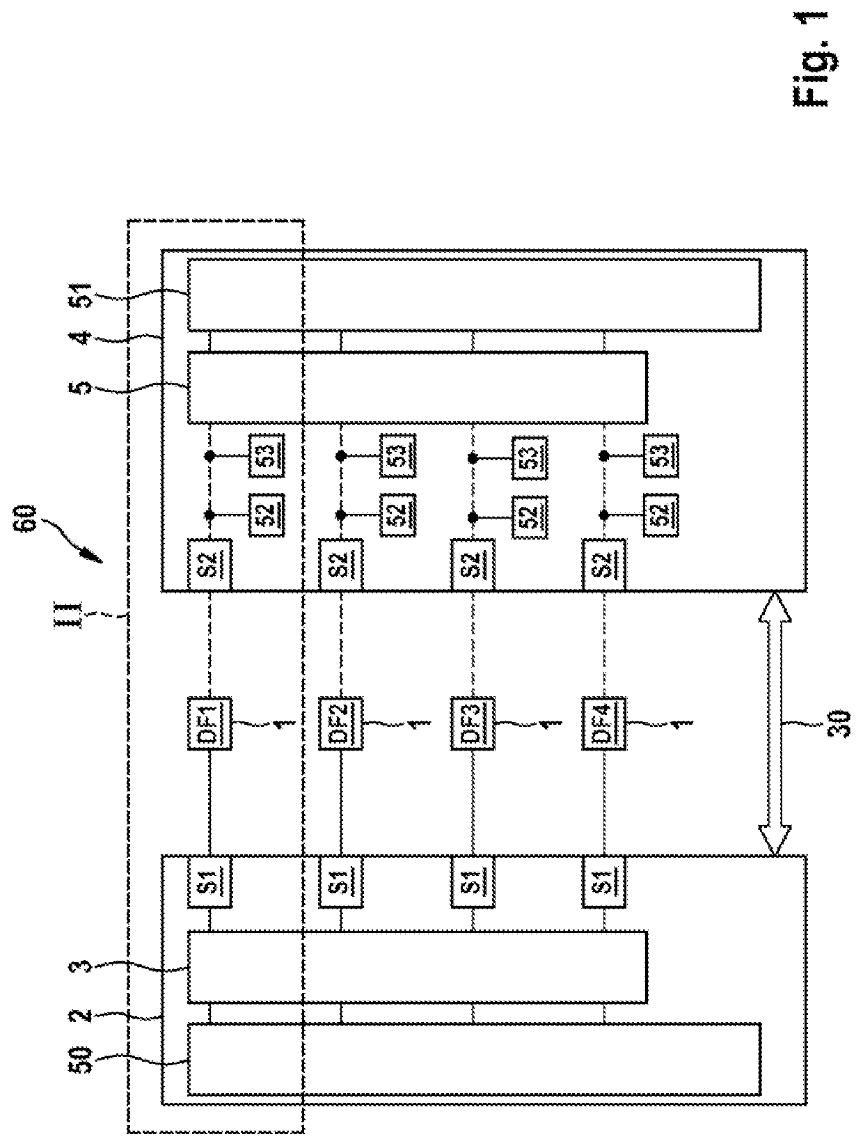
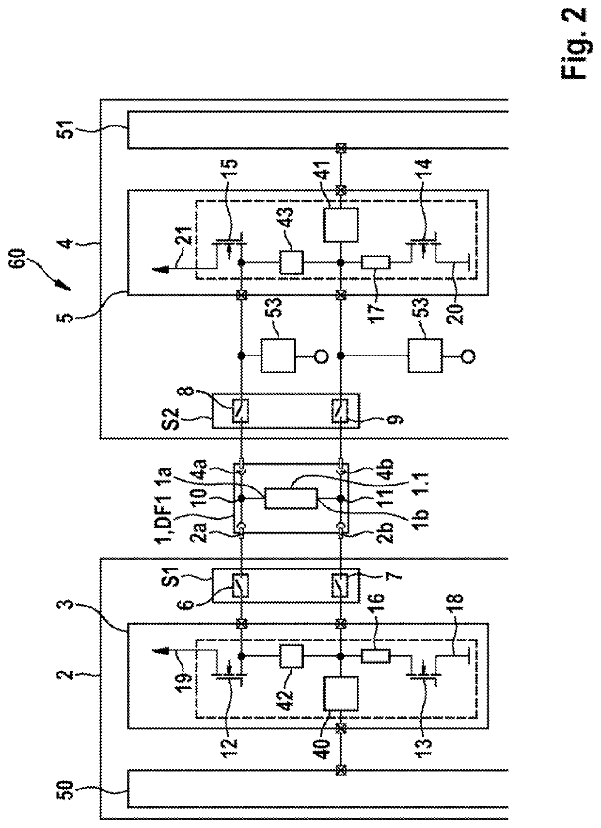
[0026]As can be seen from FIGS. 1 and 2, the depicted exemplary embodiment of a redundant sensor arrangement 60 of a vehicle system comprises two controllers and multiple sensors 1. The individual sensors 1, in a normal mode of the vehicle system, are each coupled to a controller embodied as a primary controller 2 and, in an emergency mode of the vehicle system, are each coupled to a controller embodied as a secondary controller 4 and are supplied with power. In this instance, the controller that is coupled to the sensors 1 receives and evaluates signals from the individual sensors 1. As can furthermore be seen from FIGS. 1 and 2, the redundant sensor arrangement 60 in the depicted exemplary embodiment comprises four sensors 1, embodied as speed sensors DF1, DF2, DF3, DF4, that each have a sensor element 1.1. As can furthermore be seen from FIG. 1, the individual sensors 1 embodied as speed sensors DF1, DF2, DF3, DF4 can each be connected to evaluation electronics of the primary con...


PUM


Abstract

An operating method for a redundant sensor arrangement of a vehicle system including a primary controller, a secondary controller and multiple sensors, wherein the individual sensors, in a normal mode of the vehicle system, are each coupled to the primary controller and, in an emergency mode of the vehicle system, are each coupled to the secondary controller and are supplied with power, wherein the controller that is coupled to the sensors receives and evaluates signals from the individual sensors, includes applying an operating voltage to both controllers and coupling the sensors to the primary controller and checking the coupled sensors with the primary controller. The secondary controller, in the decoupled state, checks its internal voltage supply and at least one internal signal path. Then, the secondary controller is connected to the sensors to checking their power supply. The system initialization is concluded when no errors have occurred.

Description

[0001]The invention is based on an operating method for a redundant sensor arrangement of a vehicle system of the type in question in independent patent claim 1. Moreover, the invention relates to a redundant sensor arrangement for a vehicle system.[0002]DE 10 2015 202 335 A1 discloses a wheel sensor apparatus that comprises a first sensor element, by means of which at least one first sensor variable for a speed and / or rotation velocity of the wheel is providable to at least one evaluation and / or control apparatus of the vehicle, and an additional second sensor element. In this instance, at least one second sensor variable for the speed and / or rotation velocity of the same wheel is providable to the at least one evaluation and / or control apparatus by means of the second sensor element.[0003]DE 10 20 14 208 391 A1 discloses an apparatus for operating a vehicle, which apparatus comprises a coupling device designed to decouple a speed sensor from a primary power supply of a primary con...

Claims


Application Information

Patent Timeline
Patent Type & Authority Applications(United States)
IPC IPC(8): B60W50/023B60W50/02B60T8/171B60T17/22B60T8/88
CPCB60W50/023B60W50/0205B60T8/171B60T2270/413B60T8/885B60T2270/402B60T2270/406B60T17/221B60W50/04B60T17/22B60Y2400/30
Inventor PLECKO, SVENXIE, FEIKOEBL, FLORIANDURAN, DANIEL RUIZ
Owner ROBERT BOSCH GMBH
Why Eureka
Try Eureka