Current transformer structure

A current transformer and electrical technology, applied in the direction of transformers, fixed transformers, transformer/inductor cores, etc., can solve the problems of short electrical safety distance between secondary winding and magnetic core group, poor safety, etc.

Active Publication Date: 2011-05-18
DELTA ELECTRONICS INC
View PDF0 Cites 0 Cited by
  • Summary
  • Abstract
  • Description
  • Claims
  • Application Information

AI Technical Summary

Problems solved by technology

[0006] The main purpose of the present invention is to provide a current transformer structure to solve the problem that the existing current transformer cannot maintain basic insulation with the secondary winding due to the primary winding and the magne...

Method used


Image

  • Current transformer structure
  • Current transformer structure
  • Current transformer structure

Examples


Embodiment Construction

[0031] Some typical embodiments embodying the features and advantages of the present invention will be described in detail in the description in the following paragraphs. It should be understood that the present invention is capable of various changes in different forms without departing from the scope of the present invention, and that the description and drawings thereof are illustrative in nature and not intended to limit the present invention.

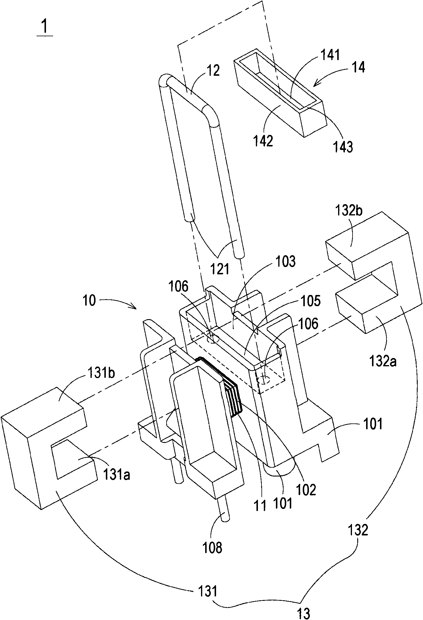
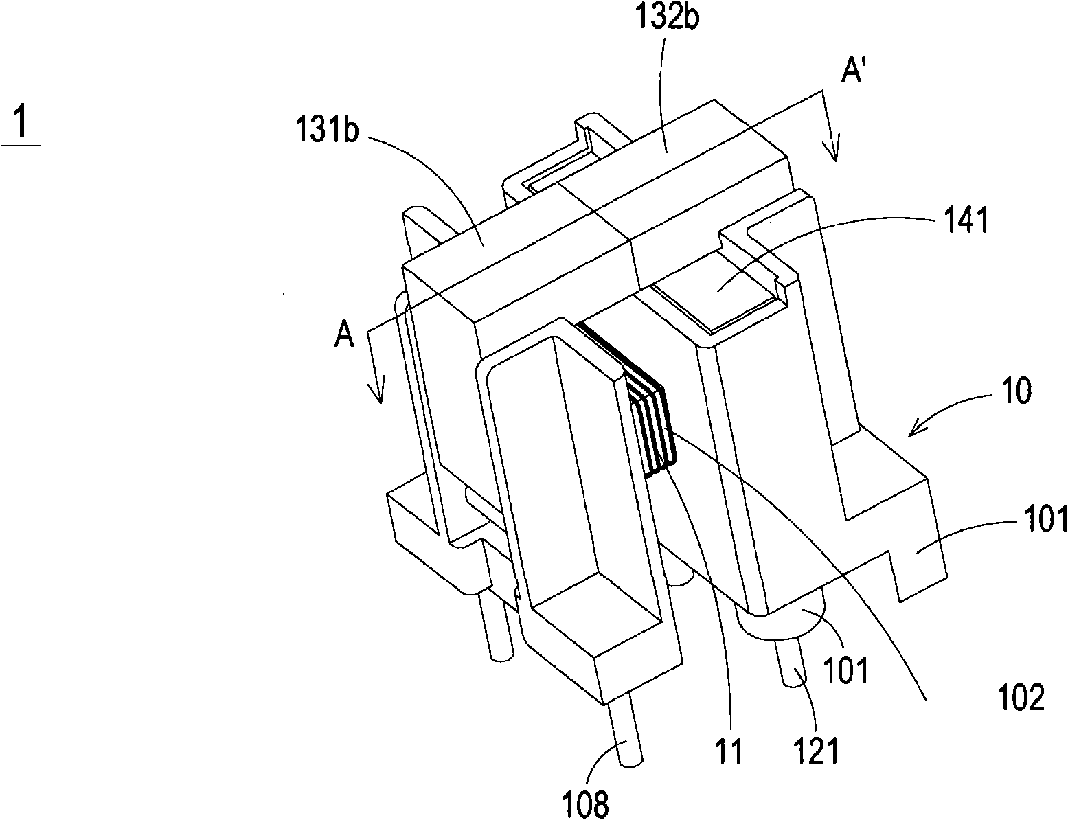
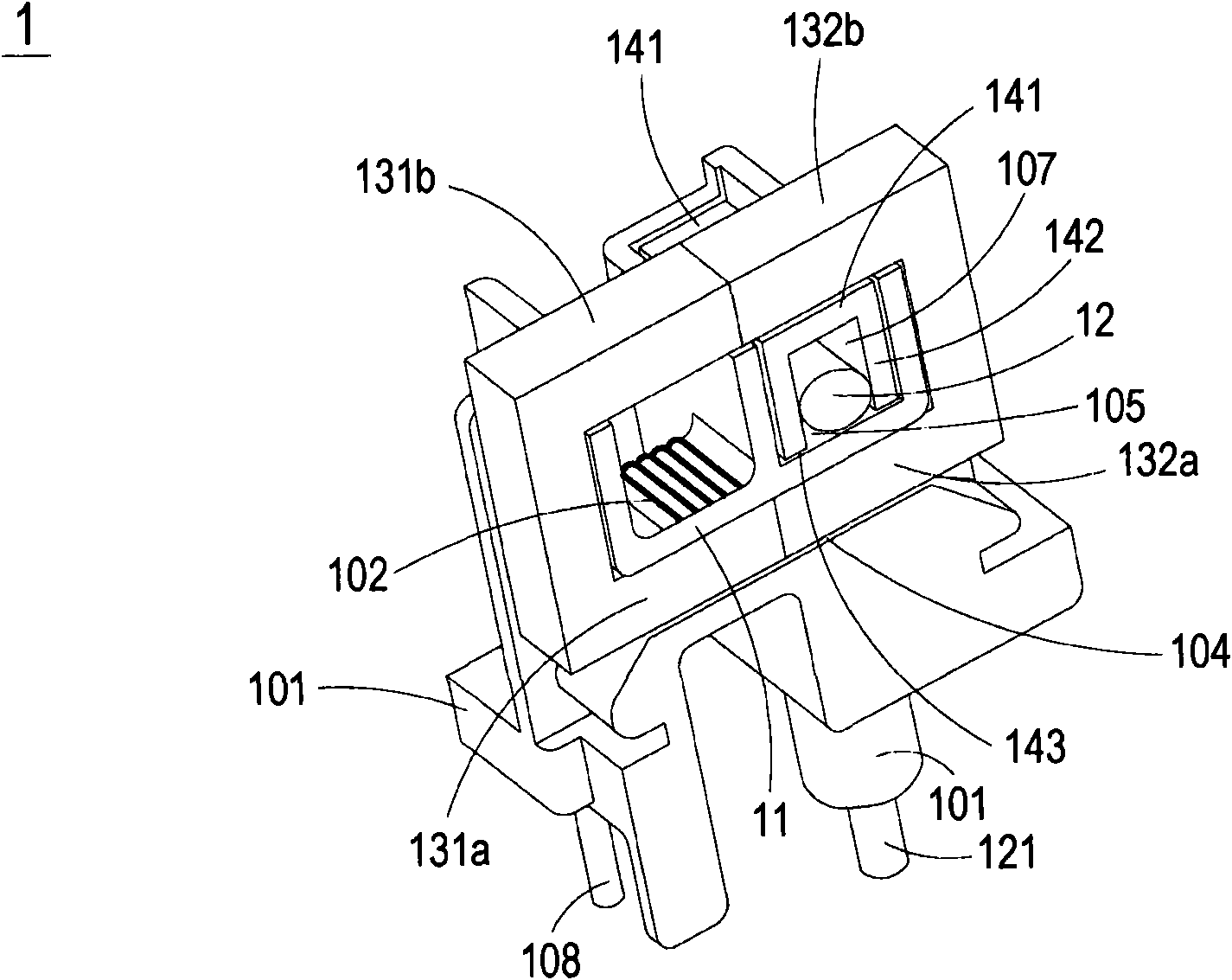
[0032] see Figure 1 to Figure 3 ,in figure 1 and figure 2 It is a schematic diagram of the decomposition structure and combined structure of the current transformer structure of the first preferred embodiment of the present invention, and image 3 for figure 2 The schematic diagram of the cross-sectional structure of the current transformer structure shown at A-A'. Such as Figure 1 to Figure 3 As shown, the current transformer 1 of the present invention includes a winding base 10 , a primary winding 11 , a conductive post ...


PUM


Abstract

The invention provides a current transformer structure. The current transformer structure comprises a winding base, a primary winding, an electric conduction column, a magnetic core assembly and a cover body, wherein the winding base is provided with a body and a groove; the body is provided with a run-through passage; the groove is formed on the body; the primary winding is wound on the body of the winding base; the electric conduction column is partially accommodated in the groove; the magnetic core assembly is provided with a first magnetic core and a second magnetic core which are partially accommodated in the run-through passage; the second magnetic core is arranged adjacent to the groove; the cover body is matched with the groove to cover the electric conduction column, so that the electric conduction column is separated from the second magnetic core respectively; moreover, the electric creepage distance between the electric conduction column and the primary winding and the electric creepage distance between the electric conduction column and the magnetic core assembly are increased.

Description

technical field [0001] The invention relates to a current transformer structure, especially a current transformer structure which uses a cover or insulating glue to increase the electrical creepage distance between internal components. Background technique [0002] A current transformer is an electronic component frequently used in various electronic products, which is used to convert the received current into a current of another proportion, so as to provide it to other electronic components for use. [0003] The existing current transformer mainly includes a winding base, a magnetic core group, primary winding and secondary winding, wherein the primary winding and the secondary winding are separately wound on the winding area of ​​the winding base, and The magnetic core group partly penetrates the winding area of ​​the winding base. In this way, when a current is passed through the primary winding, the magnetic core group can induce a magnetic field, thereby generating an ...

Claims


Application Information

Patent Timeline
IPC IPC(8): H01F30/06H01F27/30H01F27/24H01F27/29H01F27/36H01F27/32
Inventor 赖信宗廖高材张治良
Owner DELTA ELECTRONICS INC
Why Eureka
Try Eureka