Eureka AIR delivers breakthrough ideas for toughest innovation challenges, trusted by R&D personnel around the world.

Wheel rim drive-type omnidirectional wheel capable of measuring feedback by using inductance angle displacement

A displacement measurement and wheel drive technology, applied in the field of omnidirectional wheels, can solve the problems of high cost, inaccurate angular displacement measurement, complex structure of omnidirectional wheel steering mechanism, etc., and achieve the effect of simple and compact construction and high measurement accuracy.

Inactive Publication Date: 2011-05-25
SOUTHEAST UNIV
View PDF3 Cites 17 Cited by
  • Summary
  • Abstract
  • Description
  • Claims
  • Application Information

AI Technical Summary

Problems solved by technology

[0004] The technical problem to be solved by the present invention is that the structure of the existing steering mechanism of the omnidirectional wheel is complicated, the angular displacement measurement is inaccurate, or the cost is too high to ensure the accuracy of the angular displacement measurement

Method used


Image

  • Wheel rim drive-type omnidirectional wheel capable of measuring feedback by using inductance angle displacement
  • Wheel rim drive-type omnidirectional wheel capable of measuring feedback by using inductance angle displacement
  • Wheel rim drive-type omnidirectional wheel capable of measuring feedback by using inductance angle displacement

Examples


Embodiment Construction

[0013] The present invention will be further described below in conjunction with accompanying drawing.

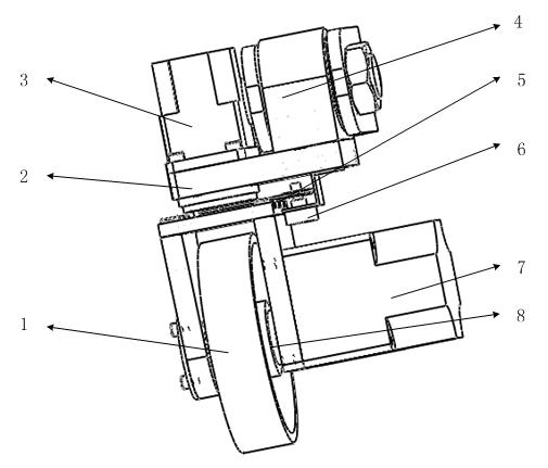
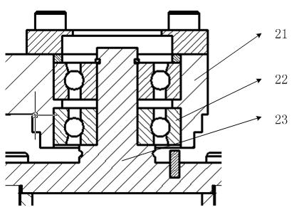
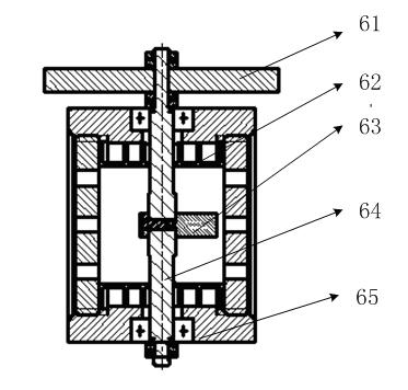
[0014] Such as figure 1 , figure 2 with image 3 As shown, the present invention includes a wheel shaft 8, a wheel 1 sleeved on the wheel shaft 8, a reversing mechanism 2 connected to the wheel shaft 8, a rudder motor 3 connected to the reversing mechanism 2, positioned on the side of the wheel 1 and connected to the reversing mechanism. The inductive angular displacement sensor 6 connected to the mechanism 2; the inductive angular displacement sensor 6 includes a casing 65, a sensor shaft 64 running through the two ends of the casing 65, a coil located in the casing 65, a skeleton 62 and a magnetic core 63; the magnetic core 63 is connected to the sensor shaft 64 , the coil and the skeleton 62 are sleeved in the shell, the coil and the skeleton 62 include two main coils and two secondary coils, the outline of the magnetic core 63 is composed of two symmetrical Archimede...


PUM


Abstract

The invention discloses a wheel rim drive-type omnidirectional wheel capable of measuring feedback by using inductance angle displacement. The wheel rim drive-type omnidirectional wheel comprises a wheel shaft, a wheel, a reversing mechanism, a rudder direction motor and an inductance angle displacement sensor, wherein the wheel is sleeved on the wheel shaft; the reversing mechanism is connected with the wheel shaft; the rudder direction motor is connected with a reversing mechanism; the inductance angle displacement sensor is positioned on one side of the wheel and is connected with the reversing mechanism; the inductance angle displacement sensor comprises a shell, a sensor rotating shaft, a coil, a skeleton and a magnetic core; the sensor rotating shaft runs through the two ends of the shell; the coil and the skeleton are positioned in the shell; the magnetic core is connected with the sensor rotating shaft; the coil and the skeleton are sleeved on the sensor rotating shaft; the coil and the skeleton comprise two primary coils and two secondary coils; the outline of the magnetic core consists of two symmetrical Archimedes spiral lines; when the magnetic core rotates, the length of the magnetic coil extending into the coil is changed along with the rotation and the length change size is in direct proportion to the rotating angle; an output shaft of a drive motor is coincident with the axis of the wheel, is connected with a wheel axle, and drives the wheel to rotate; and the rudder direction motor is vertical to the axis of the wheel, is connected with the wheel axle through the reversing mechanism, and drives the wheel to change directions. The wheel rim drive-type omnidirectional wheel has a simple and compact structure and high measuring accuracy, and can control the wheel omnidirectionally.

Description

technical field [0001] The invention relates to an omnidirectional wheel, in particular to a wheel edge driven omnidirectional wheel which adopts inductive angular displacement measurement and feedback. Background technique [0002] In recent years, with the development of mobile robotics and related technologies, the application of mobile robots in many industries has gradually deepened and broadened. An object moving on a plane can achieve three degrees of freedom of front and back, left and right, and rotation, which is called an omnidirectional mobile robot. It can not only move in any direction, and keep the posture of the body unchanged, but also change the orientation of the body like a normal vehicle. At present, omnidirectional mobile has been applied in various fields. The industrial direction is mainly for the all-round industrial product transmission system and the all-round forklift for the factory, and the working environment is relatively ideal. The laborat...

Claims


Application Information

Patent Timeline
IPC IPC(8): B60B33/00G01D5/14G01B7/30
Inventor 王兴松吴继平
Owner SOUTHEAST UNIV
Why Eureka
Eureka Blog
Learn More