Front and back lock

A technology of front lock cylinder and rear lock cylinder, which is applied in the field of tumbler locks, can solve the problems of poor anti-theft performance, easy slipping and idling, inconvenient use, etc., and achieve the effect of improving quality, improving accuracy and stability, and facilitating manufacturing

Inactive Publication Date: 2011-06-01
谢煜光
View PDF6 Cites 220 Cited by
  • Summary
  • Abstract
  • Description
  • Claims
  • Application Information

AI Technical Summary

Problems solved by technology

[0002] The current tumbler locks generally have poor anti-theft performance. There is a tumbler lock with a front and rear lock cylinder with better anti-theft performance. The patent number is ZL2008200093307. There are special-shaped marbles with side wall notches in the front lock cylinder. There are side pinholes in the front lock cylinder that communicate with the pinholes. There are side pinholes in the side pinholes. There is a rear lock cylinder behind the front lock cylinder. The rear pin hole corresponding to the rear end of the side pin hole has a locking pin in the rear pin hole, and the lock body has a locking pin hole corresponding to the locking pin
The lock is easy to slip and idle when unlocked with a key, causing inconvenience in use

Method used


Image

  • Front and back lock
  • Front and back lock
  • Front and back lock

Examples


Embodiment Construction

[0016] The embodiments will be further described below in conjunction with the accompanying drawings.

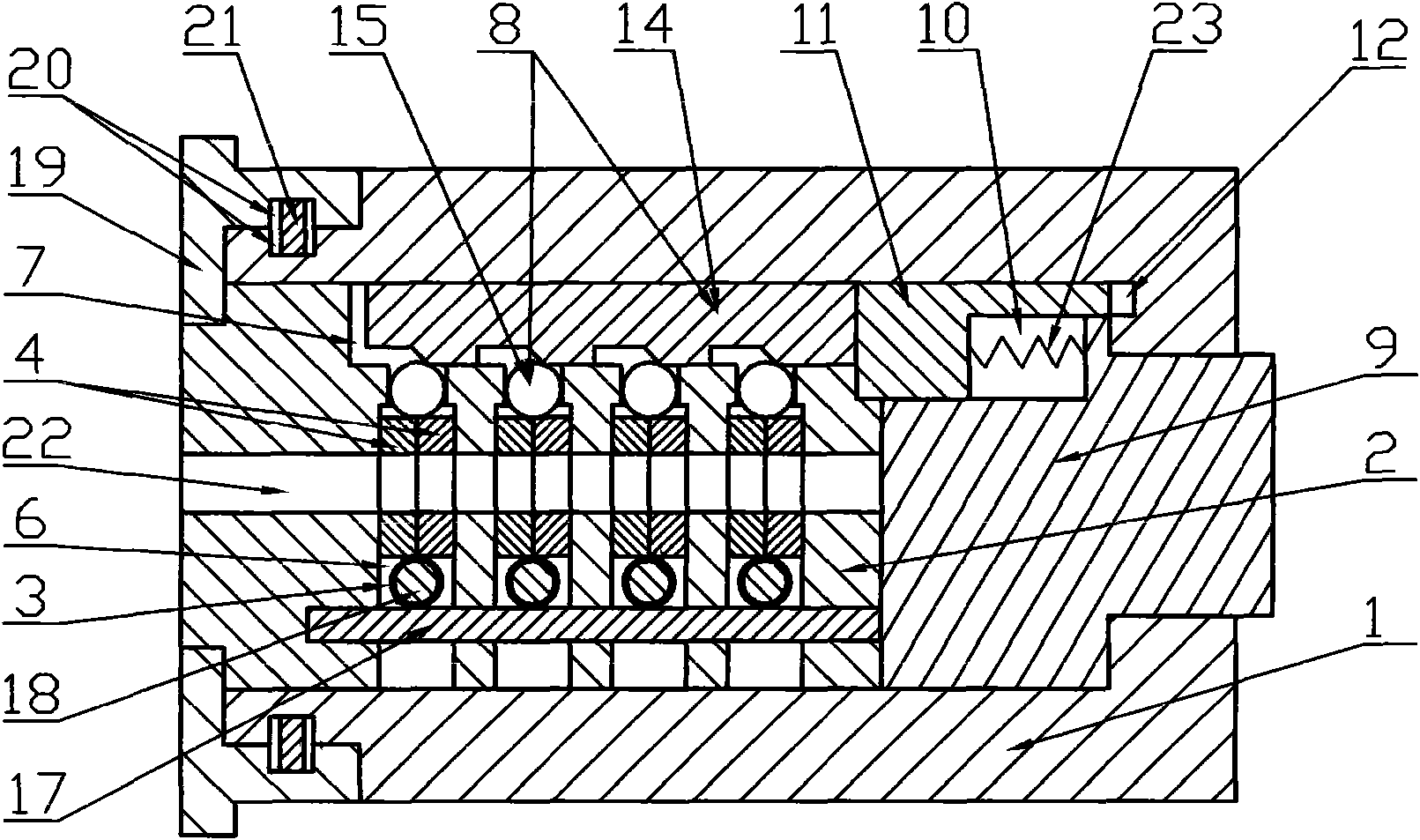
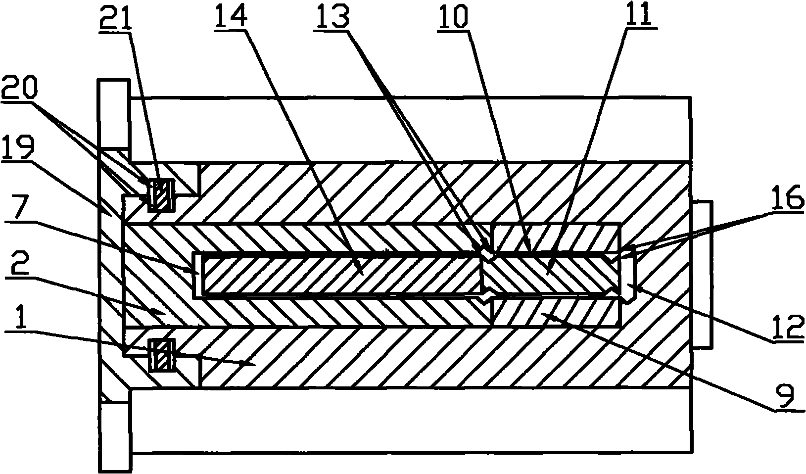
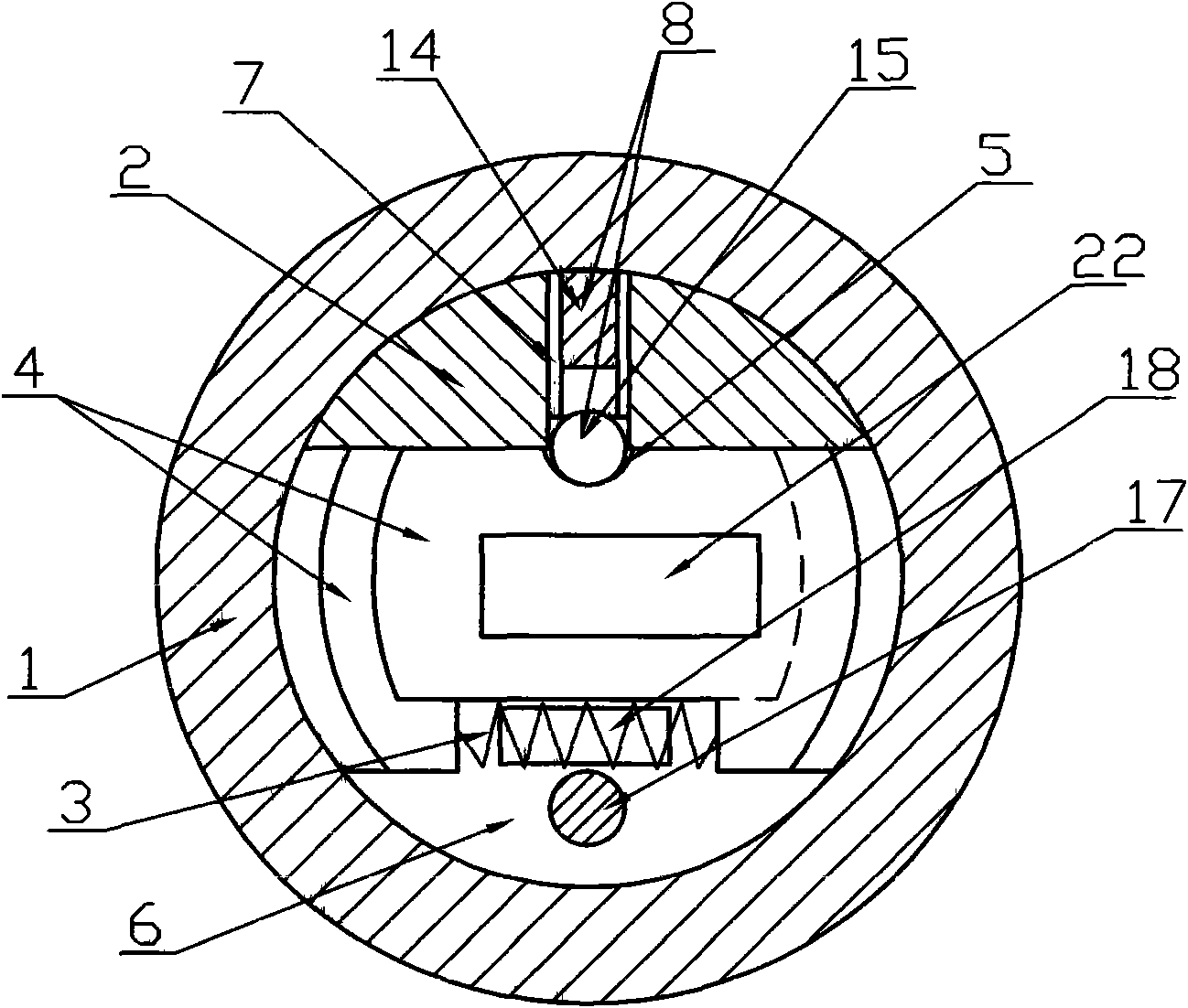
[0017] In the front and rear locks of the present invention, there are four opening through grooves perpendicular to the keyhole (22) on the front lock cylinder (2) in the lock body (1), and four through grooves are formed by long pins (17) penetrating each through groove. pinholes (6), each pinhole (6) has a group of two sheet-shaped special-shaped pins (4) with side wall gaps (5), and a spring is arranged between each group of special-shaped pins (4) (3), pin (18) is worn in the middle of spring (3), and the profile of marble hole (6) and special-shaped marble (4) cooperates mutually, and each marble hole (6) all communicates with keyhole (22). The front lock cylinder (2) has an elongated side pin hole (7), which communicates with each pin hole (6) respectively, and there is a lock bolt (14) in the side pin hole (7). Combined side pin (8) formed with four spherical balls ...


PUM


Abstract

The invention discloses a front and back lock comprising a lock body (1), a front lock cylinder (2), a spring (3) and a keyhole (22); the front lock cylinder (2) is internally provided with an atypical spring (4) with a side wall notch (5); the front lock cylinder (2) is internally provided with a side spring hole (7) communicated with a spring hole (6); the side spring hole (7) is internally provided with a side spring (8); a rear lock cylinder (9) is arranged in the rear of the front lock cylinder (2) and is provided with a rear spring hole (10) corresponding to the rear end of the side spring hole (7); the rear spring hole (10) is internally provided with a lock spring (11); and the lock body (1) is internally provided with a lock body spring hole (12) corresponding to the lock spring (11). The front and back lock is characterized in that a sharp corner (13) is arranged at the front end of the lock spring (11), or the sharp corners (13) are simultaneously arranged at the front end of the lock spring (11) and the rear end of the side spring hole (7). The lock ensures the stable leakage of the front lock cylinder (2) and the rear lock cylinder (9) by utilizing the mutual occlusion of the sharp corner (13) at the front end of the lock spring (11) and the sharp corner (13) at the rear end of the side spring hole (7). When the lock is unlocked by using an unlocking tool, the front lock cylinder (2) is idle, thereby effectively preventing from being twisted and pulled by the unlocking tool and rotated by external force to open and increasing the safety of the lock.

Description

1. Technical field [0001] The invention relates to a pin lock with side pins, in particular to a pin lock with front and rear lock cylinders, which is widely applicable to occasions with high anti-theft performance requirements. 2. Technical Background [0002] The current tumbler locks generally have poor anti-theft performance. There is a tumbler lock with a front and rear lock cylinder with better anti-theft performance. The patent number is ZL2008200093307. There are special-shaped marbles with side wall notches in the front lock cylinder. There are side pinholes in the front lock cylinder that communicate with the pinholes. There are side pinholes in the side pinholes. There is a rear lock cylinder behind the front lock cylinder. There is a locking pin in the rear pin hole corresponding to the rear end of the side pin hole, and there is a locking pin hole corresponding to the locking pin in the lock body. This lock is easy to slip idly when unlocking with a key, causin...

Claims


Application Information

Patent Timeline
Patent Type & Authority Applications(China)
IPC IPC(8): E05B27/00E05B15/10
Inventor 谢煜光
Owner 谢煜光
Why Eureka
Try Eureka