Antiskid differential

A technology of anti-slip differentials and moving rings, which is applied in the direction of differential transmissions, belts/chains/gears, mechanical equipment, etc., can solve problems such as complex meshing of internal structures, influence on use effects, and increased process requirements, and achieve ingenious design , Improve passing capacity, solve the effect of slipping and idling

Active Publication Date: 2017-05-31
CHANGZHOU VOCATIONAL INST OF ENG
View PDF7 Cites 3 Cited by
  • Summary
  • Abstract
  • Description
  • Claims
  • Application Information

AI Technical Summary

Problems solved by technology

However, although this application has improved the meshing method of the jaw differential, its internal structure is still relatively complicated, and there are many internal parts of the differential, which require close cooperation, and the mechanism is easy to wear. If the wear conditions are different, the parts There may be mutual interference, which will affect the use effect and shorten the service life; and if special materials are used, the price will increase and the process requirements will also increase

Method used


Image

  • Antiskid differential
  • Antiskid differential
  • Antiskid differential

Examples


Embodiment 1

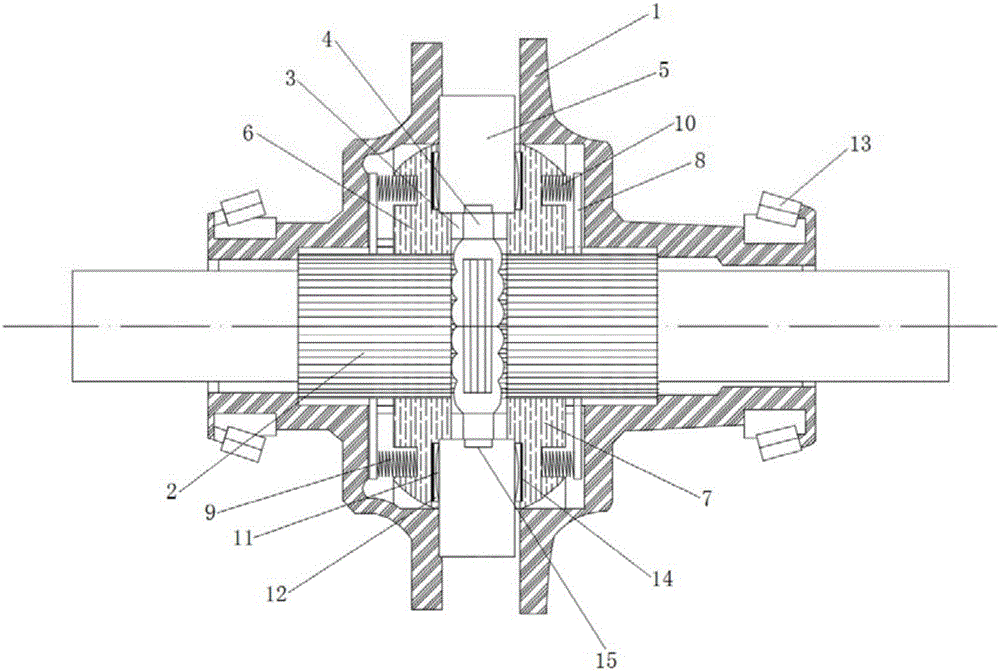
[0028] combine figure 1 As shown, a non-slip differential in this embodiment includes an outer shell 1, a half shaft spline hub 2, a center ring 4, a driving ring 5, a left driven ring 6, a right driven ring 7, a spring seat 8, The left auxiliary spring 9 and the right auxiliary spring 10, the outer shell 1 adopts a two-lobe structure, and is connected by bolts as an integral structure. The outer shell 1 also has a transmission mechanism connected with the output shaft of the engine. Two sets of half-shaft spline hubs 2 are used to externally connect the left and right wheel half-shafts. The left and right wheel half-shafts are splined to the corresponding half-shaft spline hubs 2, which is easy to install and has a large transmission torque; the two sets of half-shaft spline hubs The inner ends of 2 are each equipped with a snap ring 3, the center ring 4 is installed between the two snap rings 3, the center ring 4 is limited between the two snap rings 3 and cannot move axiall...

Embodiment 2

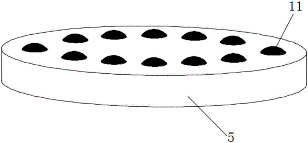
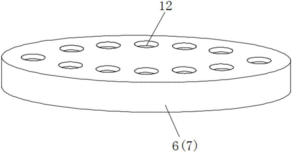
[0032] A non-slip differential of this embodiment has the same basic structure as that of Embodiment 1, except that in this embodiment, the locking teeth structure includes concave locking teeth 12 uniformly arranged on the outer wall of the driving ring 5, uniformly The convex locking teeth 11 located on the inner side walls of the left driven ring 6 and the right driven ring 7, the convex locking teeth 11 are protrusions of a spherical structure, and the concave locking teeth 12 are grooves of a cylindrical structure. The latch teeth 12 are meshed. The locking tooth structure can also play a role similar to that of the locking tooth structure in Embodiment 1.

[0033] In order to better understand the content of the present invention, now in conjunction with figure 1 Set forth the working principle of a kind of limited slip differential of above-mentioned embodiment 1 and embodiment 2:

[0034] When in use, the torque of the engine is transmitted to the outer casing 1, whi...


PUM


Abstract

The invention discloses an antiskid differential and belongs to the field of automobile parts. According to the antiskid differential, two half-shaft spline hubs externally connected with a left wheel half shaft and a right wheel half shaft are mounted in the middle of an outer shell. A center ring is mounted at the inner side ends of the two half-shaft spline hubs through clamping rings. The outer side of the center ring is sleeved with the inner side of a driving ring. A left driven ring and a right driven ring are mounted on the two sides of the driving ring in an engaged manner. The left driven ring and the right driven ring are engaged and connected with the half-shaft spline hubs on the corresponding sides. The outer side wall of the left driven ring and the outer side wall of the right driven ring are each provided with an auxiliary spring. Clamping tooth mechanisms which can be in engaged transmission and can make the driven ring on the fast rotation side and the driving ring disengaged from each other when a certain rotating speed difference exists between the left driven ring and the right driven ring are correspondingly arranged between the driving ring and the left driven ring and between the driving ring and the right driven ring. The differential is simple in structure, ingenious in design, convenient to use and reliable to work, the problems of sliding and idling of the wheels can be well solved when the automobile drives on the suspension sliding road, and the passing capacity of the automobile is improved remarkably.

Description

technical field [0001] The present invention relates to an automobile differential, more specifically, to a non-slip differential. Background technique [0002] Differentials are mainly used in automobile transmission systems. Ordinary differentials are composed of planetary gears, planetary gear carriers (housings), side gears and other parts. The power of the engine enters the differential through the transmission shaft and directly drives the planetary gear carriers. , and then the planetary wheel carrier drives the left and right axle shafts to drive the left and right wheels respectively. When the car is going straight, the speeds of the left and right wheels and the planetary wheel frame are equal to maintain a balanced state. When the car turns, the balance is broken, the speed of the outer wheel increases, and the inner wheel The speed is reduced to realize the speed difference and achieve automatic adjustment. However, when encountering rough and muddy road conditi...

Claims


Application Information

Patent Timeline
Patent Type & Authority Applications(China)
IPC IPC(8): F16H48/12F16H48/38
CPCF16H48/12F16H48/38
Inventor 于瑞姜淑华
Owner CHANGZHOU VOCATIONAL INST OF ENG
Why Eureka
Try Eureka