
Shell of driving roller

A technology for driving rollers and shells, applied in the direction of pipes/pipe joints/fittings, special pipes, mechanical equipment, etc., can solve the problems of high replacement costs, achieve the effects of increasing contact surface, preventing slipping and idling, and increasing friction

Active Publication Date: 2018-02-16
南京管科智能科技有限公司
View PDF8 Cites 4 Cited by
  • Summary
  • Abstract
  • Description
  • Claims
  • Application Information

AI Technical Summary

Problems solved by technology

[0003] The purpose of the present invention is to provide a shell of a driving drum, which solves the technical problem of high replacement cost due to the integrated structure of the shell and the drum body of the spiral drum in the prior art

Method used


Image

  • Shell of driving roller
  • Shell of driving roller
  • Shell of driving roller

Examples


Embodiment 1

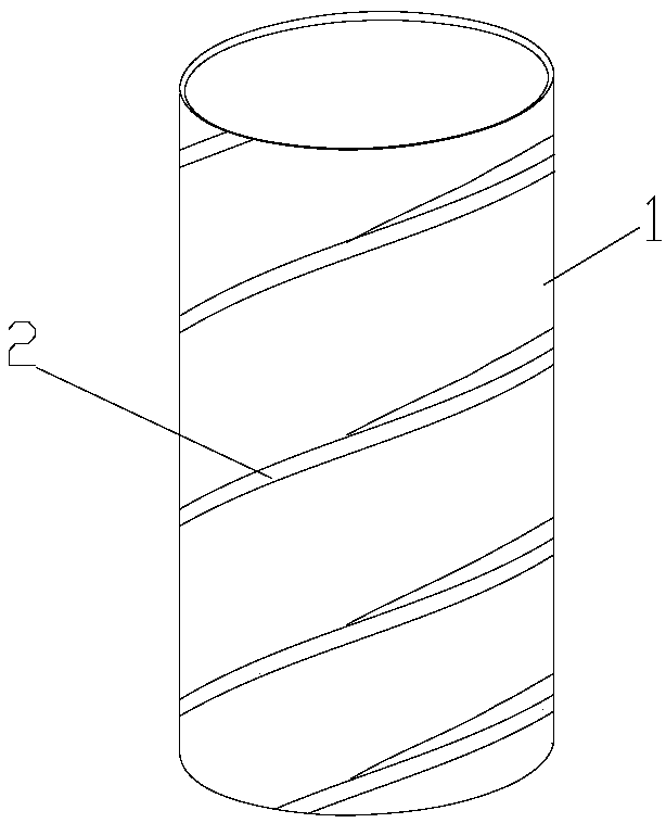
[0037] like figure 1 As shown, a shell 1 of a driving drum is shown. The shell 1 is cylindrical, and the outer peripheral surface of the shell is fixedly provided with a helical blade 2 along its length direction. The shell is integrally formed and straight. If the driving roller is a columnar body, it is very convenient to assemble. It only needs to cover the outer shell on the driving roller. The blades on the outer peripheral surface of the housing 1 are in a continuous spiral shape. The pitch of the helical blade is 5cm, the height of the helical blade is 3cm, and the width of the helical blade is 2cm.

Embodiment 2

[0039] In this embodiment, the shell is divided into two halves by a plane perpendicular to its axis, and is two straight cylinders. When assembling, the two half shells are respectively sleeved on the driving roller from the ends. The blades on the outer peripheral surface of the housing 1 are in a continuous spiral shape. In other embodiments, the shell is divided into two frustoconical shells by a plane perpendicular to its axis.

Embodiment 3

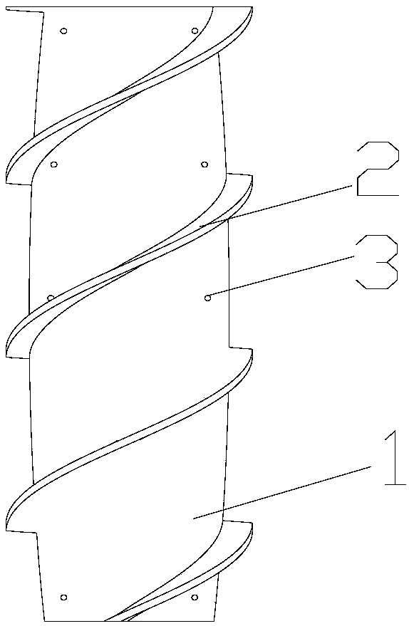
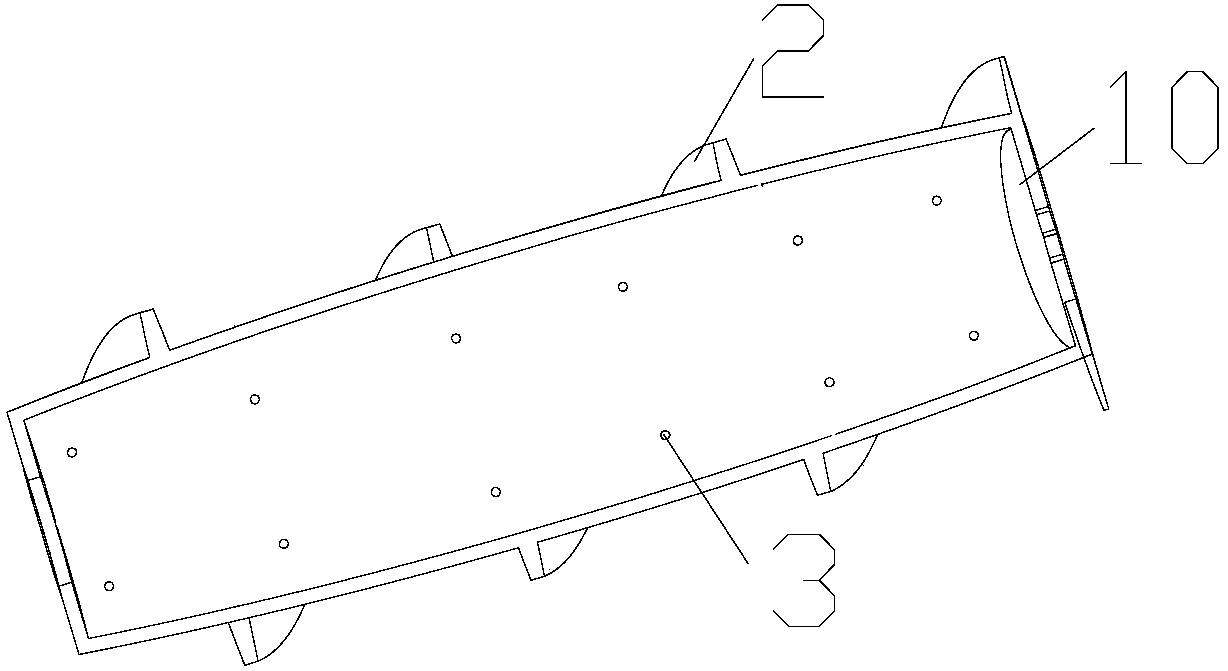
[0041] like figure 2 , 3 As shown, in this embodiment, the housing 1 is divided into two halves along the axial direction. The inner wall of the housing is a smooth arc surface, and the housing is provided with threaded holes 3 for fixing the housing and the driving drum, and the housing and the driving drum are fixed by screws, which is convenient for disassembly. The blades on the outer peripheral surface of the housing 1 are in a continuous spiral shape. The pitch of the helical blade 2 is 8cm, the height of the helical blade 2 is 3cm, and the width of the helical blade 2 is 2cm.

[0042] Both ends of the housing are provided with head plates 10 to prevent water or dirt from entering the gap between the housing and the driving drum.

[0043] The shell 1 is in the shape of a tapered shuttle and includes three sections: a straight barrel section in the middle and a frustum shell section at both ends, and the three sections are integrally formed. Tapered shuttle-shaped de...


PUM


Abstract

The invention discloses a shell of a driving roller. According to the shell of the driving roller, a shell body is cylindrical; a screw blade is fixedly arranged on the outer peripheral surface of theshell body in the length direction of the shell body; the shell body is fixedly arranged outside the driving roller in a sleeving mode, when a pipeline robot works, the shell body rotates along withthe driving roller, when a roller of the robot makes contact with the inner wall of a pipeline, sludge in the pipeline or the like, friction is generated between the screw blade and the inner wall ofthe pipeline or the sludge so that the pipeline robot can be driven to move forward, and the contact area is large so that slipping can be avoided; when the roller of the robot is suspended in water,the screw blade is equivalent to a propeller and rotates to drain away water backwards so as to drive the pipeline robot to move forward; and the screw blade is large in abrasion amount and high in abrasion, and when the screw blade is excessively abraded, the driving capacity is greatly reduced, so that the screw blade should be replaced periodically. The shell of the driving roller has the advantages that the shell body and the driving roller body are designed in a split mode, only the shell body needs to be replaced regularly, the driving roller does not need to be replaced, and therefore the cost is greatly reduced.

Description

technical field [0001] The invention relates to a casing of a driving drum. Background technique [0002] The environment of municipal pipelines is very harsh, and after long-term use, it is prone to corrosion, fatigue damage, or potential internal defects of the pipeline to develop into damage and cause leakage accidents, etc., especially for water pipelines, which are also prone to blockage and other accidents. Therefore, the in-pipe detection and desilting of pipelines is a very important practical project. At present, most of the in-pipe detection and decontamination are performed manually, which is limited by factors such as the size of the pipeline and the harsh environment, resulting in high work intensity and low work efficiency. For this problem, there are currently pipeline robots, such as: roller type, spiral drum type, etc. For the spiral drum type pipeline robot, the spiral drum is used as the driving part of the robot. When the spiral drum rotates, it rubs aga...

Claims


Application Information

Patent Timeline
Patent Type & Authority Applications(China)
IPC IPC(8): F16L55/32F16L101/30F16L101/12
CPCF16L55/32F16L2101/30F16L2101/12
Inventor 娄保东
Owner 南京管科智能科技有限公司
Learn More