limited slip differential

A technology of anti-skid differentials and gears, which is applied in the direction of differential transmissions, belts/chains/gears, mechanical equipment, etc. It can solve problems such as easy wear of mechanisms, increased process requirements, and failure of driving power to solve slippage The effect of idling

Active Publication Date: 2017-02-22
中国机械工业第一建设有限公司
View PDF5 Cites 0 Cited by
  • Summary
  • Abstract
  • Description
  • Claims
  • Application Information

AI Technical Summary

Problems solved by technology

However, when encountering rough and muddy road conditions, the driving wheels slip or even completely idling, the differential will waste all the driving force on the slipping wheels, so that the driving power cannot be applied to the effective wheels
[0003] Chinese patent literature discloses a "differential" (patent number CN201010264710.7 announcement date: 2010.12.1), which can provide a purely mechanical method that is completely different from the existing technical ideas. The differential device is fast and non-slip, and at the same time solves the problem of the service life of the worm gear inside the limited-slip differential. However, there are many internal parts, which require close cooperation, and the mechanism is easy to wear. If the wear conditions are different, the parts may interfere with each other. Affect the use effect and shorten the service life
If special materials are used, the price will become higher and the process requirements will also increase

Method used


Image

  • limited slip differential
  • limited slip differential
  • limited slip differential

Examples


Embodiment 1

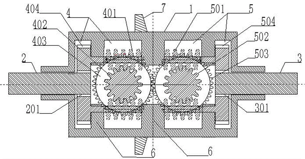
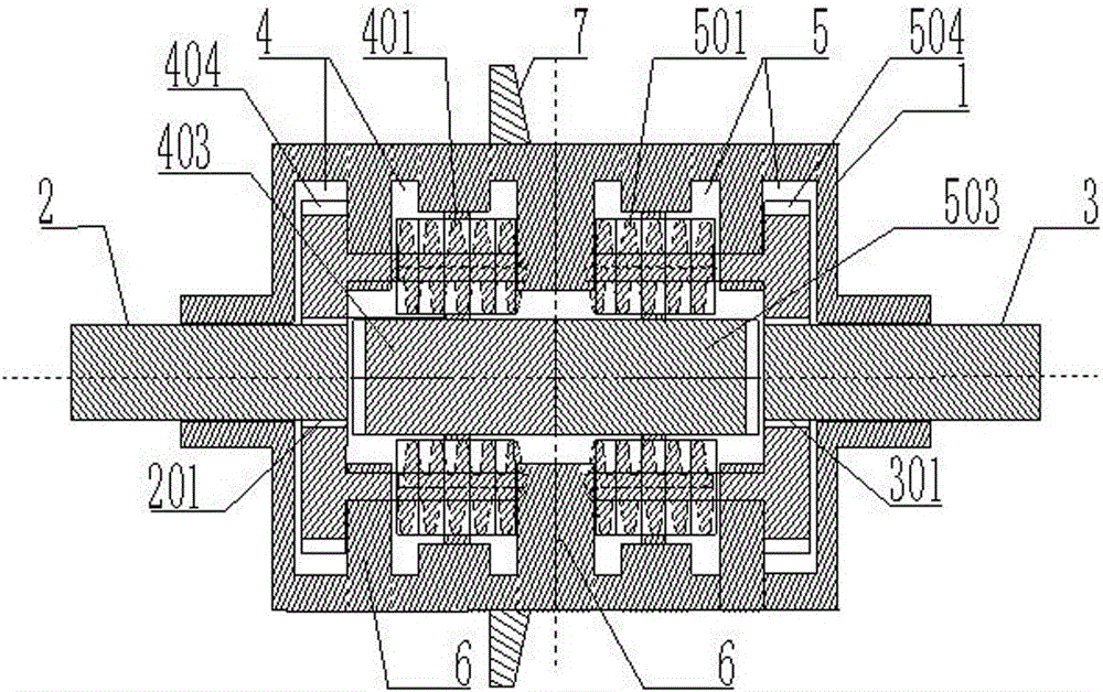
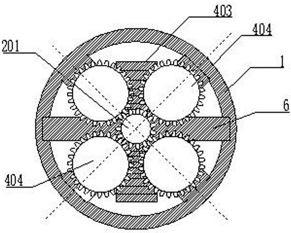
[0021] see figure 1 , figure 2 , image 3 Shown: a non-slip differential, including a housing 1, a left output half shaft 2 and a right output half shaft 3.

[0022] Wherein, the housing 1 has at least two relatively independent cavities inside. The cavity on the left side is used for assembling the left conversion part 4 , and the cavity on the right side is used for assembling the right conversion part 5 . The left output shaft 2 is assembled on the left end of the housing 1, and is connected with the left conversion part 4 assembled in the housing 1, and the right output shaft 3 is assembled at the right end of the housing 1, and is connected with the right conversion part assembled in the housing 1. Section 5 is connected.

[0023] The left conversion part 4 is mainly composed of two groups, each group of two first worms 401 (at least one group, each group is one first worm 401, but in order to ensure the stability of the transmission, generally two symmetrical groups...

Embodiment 2

[0032] The other structure of this embodiment is the same as that of Embodiment 1, the difference is that the housing of the invention is not divided into two cavities, left and right, but a housing composed of one cavity, in which there are left and right cavities. Two conversion parts.

Embodiment 3

[0034]The other structure of this embodiment is the same as that of Embodiment 2 and Embodiment 3, the difference being that the left conversion part is a group of worms and a worm wheel in the left and right conversion parts of the invention, and the right conversion part is two groups of worms and two An asymmetric arrangement consisting of two worm gears, wherein each group of worm gears is one, depending on the actual situation.


PUM


Abstract

The invention discloses a limited slip differential, which comprises a casing, a left output half shaft and a right output half shaft, wherein the left output half shaft and the right output half shaft are assembled at the left end and the right end of the casing, and a left conversion part and a right conversion part are assembled in the casing and are correspondingly engaged; the left conversion part comprises at least one group of worm and worm gear and a first gear, a third gear is arranged on the worm and is engaged with a second gear of the left output half shaft, the worm wheel is assembled in the casing through a shaft rod, and is engaged with the worm of the corresponding group, and the first gear and the worm wheel are coaxially assembled on the same shaft rod; the right conversion part comprises at least one group of worm and worm gear and a fourth gear, a sixth gear is arranged on the worm and is engaged with a fifth gear of the right output half shaft, the worm wheel is assembled in the casing through a shaft rod, and is engaged with the worm of the corresponding group, the fourth gear and the worm wheel are coaxially assembled on the same shaft rod, and the fourth gear is engaged with the first gear of the left conversion part. The limited slip differential can realize the limited slip and corrosion-resistant functions.

Description

technical field [0001] The invention relates to a mechanical transmission differential mechanism, in particular to an anti-skid differential. Background technique [0002] Differentials are mainly used in automobile transmission systems. Ordinary differentials are composed of planetary gears, planetary gear carriers (housings), side gears and other parts. The power of the engine enters the differential through the transmission shaft and directly drives the planetary gear carriers. , and then the planetary wheel carrier drives the left and right axle shafts to drive the left and right wheels respectively. When the car is going straight, the speeds of the left and right wheels and the planetary wheel frame are equal to maintain a balanced state. When the car turns, the balance is broken, the speed of the outer wheel increases, and the inner wheel The speed is reduced to realize the speed difference and achieve automatic adjustment. However, when encountering rough and muddy r...

Claims


Application Information

Patent Timeline
Patent Type & Authority Patents(China)
IPC IPC(8): F16H48/285
CPCF16H48/285
Inventor 吴秋民
Owner 中国机械工业第一建设有限公司
Why Eureka
Try Eureka