A design method for deflectable sawtooth wing leading edge

A technology of wing leading edge and design method, which is applied in design optimization/simulation, aircraft parts, geometric CAD, etc., can solve the problems of pitching moment up-up phenomenon, wing outer wing stall, sudden head-up moment, etc., to ensure the curved surface The effect of mass, simple motion form, and simple drive mechanism

Active Publication Date: 2020-09-29
JIANGXI HONGDU AVIATION IND GRP
View PDF6 Cites 0 Cited by
  • Summary
  • Abstract
  • Description
  • Claims
  • Application Information

AI Technical Summary

Problems solved by technology

[0002] As a high-speed aircraft, the wing sweep angle is generally large. Due to the wing sweep, when flying at high speed, when it reaches a certain angle of attack, the pitching moment is prone to produce instability, that is, the phenomenon of pitching up, and then cause the aircraft to lose control. Due to the stall of the outer wing of the wing, the lift force drops, which in turn causes a sudden nose-up moment; the main mechanism is that the sweep angle accelerates the low-energy airflow boundary layer on the wing surface to gather towards the wingtip. To solve this problem, wing blades and The serrated leading edge optimizes its aerodynamic flow characteristics. The wing knife is a knife-like structure installed on the upper surface of the wing along the course, which can delay the angle of attack that occurs when pitching up, but cannot eliminate it; and due to the existence of the wing knife, it is easy to cause the inner wing Stall first, the outer boundary layer still flows to the wingtip, which causes the wing to stall in advance; the design of the serrated leading edge directly affects its effect of suppressing the stall of the outer wing, and determines the optimization characteristics of the airflow of the outer wing, so how to obtain a better The key point is to optimize the aerodynamic characteristics without complicating the leading edge drive mechanism.

Method used


Image

  • A design method for deflectable sawtooth wing leading edge
  • A design method for deflectable sawtooth wing leading edge
  • A design method for deflectable sawtooth wing leading edge

Examples


Embodiment Construction

[0021] In order to make the technical means, creative features, goals and effects achieved by the present invention easy to understand, the present invention will be further described below in conjunction with specific illustrations.

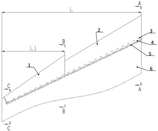
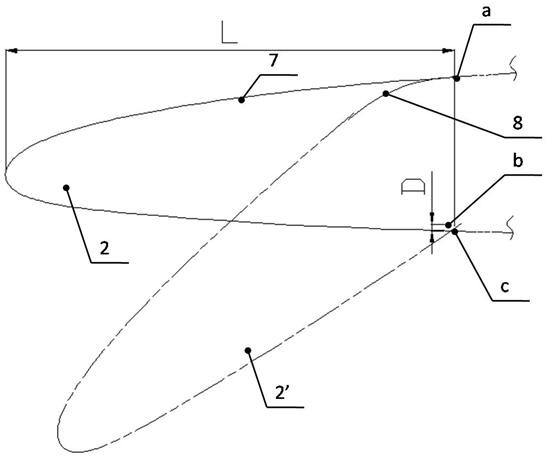
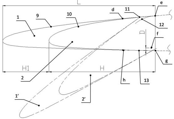
[0022] see Figure 1~4 A deflectable sawtooth wing leading edge design method, the deflectable sawtooth wing leading edge includes a serrated segment leading edge 1, a deflected serrated segment leading edge 1', an inner segment leading edge 2, and a deflected inner segment leading edge 2' , sealing plate 3, deflection shaft 4, leading edge rear boundary 5, fixed airfoil 6, the specific design steps are as follows:

[0023] 1) Determine the size parameter L of the leading edge of the airfoil curve as 3000-4000mm and the starting position L1 of the sawtooth section as 1200-1800mm. According to the design goal of the sawtooth to inhibit the flow of the boundary layer to the wingtip, generally take L1 / L to be approximately equal to 40% , in order ...


PUM


Abstract

The invention provides a design method of a deflection leading edge of a serrated wing. The deflection leading edge of the serrated wing includes a serrated segment leading edge body, an inner segment leading edge, a sealing plate, a deflection rotating shaft, a leading edge rear boundary and a fixed wing surface; the serrated segment leading edge body is formed in the steps that two section lines, namely a wing-shaped second curve and a wing-shaped fourth curve, and a wing horizontal line are subjected to multi-section scanning to form a serrated segment wing and the serrated segment wing is cut through the leading edge rear boundary; the inner segment leading edge is formed in the steps that two section lines, namely a wing-shaped first curve and a wing-shaped third curve, and a wing horizontal line are subjected to multi-section scanning to form an inner segment wing and the inner segment wing is cut through the leading edge rear boundary; excellent pneumatic flow control effect can be obtained, and the design of a driving mechanism is easily achieved. At the same time, a deflection motion design method is simple, positioning is accurate, motion forms are simple, the driving mechanism is simple, definition of the design size of the seal plate is simple, the shape of a hook face is simple, the quality of the hook face is easy to guarantee, the distance between the seal plate and the leading edge of the wing is easy to control, and it is ensured that the deflection process of the leading edge of the wing is not interfered.

Description

technical field [0001] The invention relates to the technical field of aircraft design, in particular to a design method for the leading edge of a deflectable sawtooth wing. Background technique [0002] As a high-speed aircraft, the wing sweep angle is generally large. Due to the wing sweep, when flying at high speed, when it reaches a certain angle of attack, the pitching moment is prone to produce instability, that is, the phenomenon of pitching up, and then cause the aircraft to lose control. Due to the stall of the outer wing of the wing, the lift force drops, which in turn causes a sudden nose-up moment; the main mechanism is that the sweep angle accelerates the low-energy airflow boundary layer on the wing surface to gather towards the wingtip. To solve this problem, wing blades and The serrated leading edge optimizes its aerodynamic flow characteristics. The wing knife is a knife-like structure installed on the upper surface of the wing along the course, which can de...

Claims


Application Information

Patent Timeline
Patent Type & Authority Patents(China)
IPC IPC(8): G06F30/15G06F30/20B64F5/00
CPCB64F5/00G06F30/15G06F30/20
Inventor 杨波周小勇李泰安马经忠罗松曹毅施敬杨广杨修茂刘敏
Owner JIANGXI HONGDU AVIATION IND GRP
Why Eureka
Try Eureka