A fault-tolerant control system and control method for automotive brake-by-wire failures

A fault-tolerant control, brake-by-wire technology, applied in the direction of brake control systems, brakes, brake components, etc., to achieve the effect of coordinated control and improved safety

Active Publication Date: 2021-05-25
JIANGSU UNIV
View PDF0 Cites 0 Cited by
  • Summary
  • Abstract
  • Description
  • Claims
  • Application Information

AI Technical Summary

Problems solved by technology

However, the reliability of the brake-by-wire system is more susceptible to electromagnetic interference than the traditional hydraulic brake system, and needs to be further improved.

Method used


Image

  • A fault-tolerant control system and control method for automotive brake-by-wire failures
  • A fault-tolerant control system and control method for automotive brake-by-wire failures
  • A fault-tolerant control system and control method for automotive brake-by-wire failures

Examples


Embodiment 1

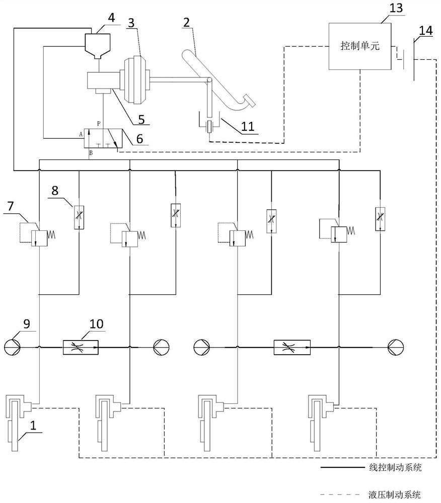
[0033] Such as figure 2 As shown, the present invention is a schematic structural diagram of a fault-tolerant control system for automobile brake-by-wire failures, including a brake 1, a brake pedal 2, a vacuum booster 3, a liquid storage tank 4, a brake master cylinder 5, a two-position three Solenoid valve 6 , boost valve 7 , control valve 8 , wheel cylinder sensor 9 , balance valve 10 , pedal angle sensor 11 , control unit 13 and battery 14 .

[0034] The vacuum booster 3 is connected between the brake pedal 2 and the brake master cylinder 5, and the liquid storage tank 4 is connected to the brake master cylinder 5; the brake pedal 2 is used for braking or releasing the brake when the vehicle needs to brake , to give the driver a certain feeling; the vacuum booster 3 is used to provide assistance for the driver’s operation of the brake pedal 2, and in the hydraulic brake system, the force of the driver stepping on the brake pedal 2 is amplified and transmitted to The brak...

Embodiment 2

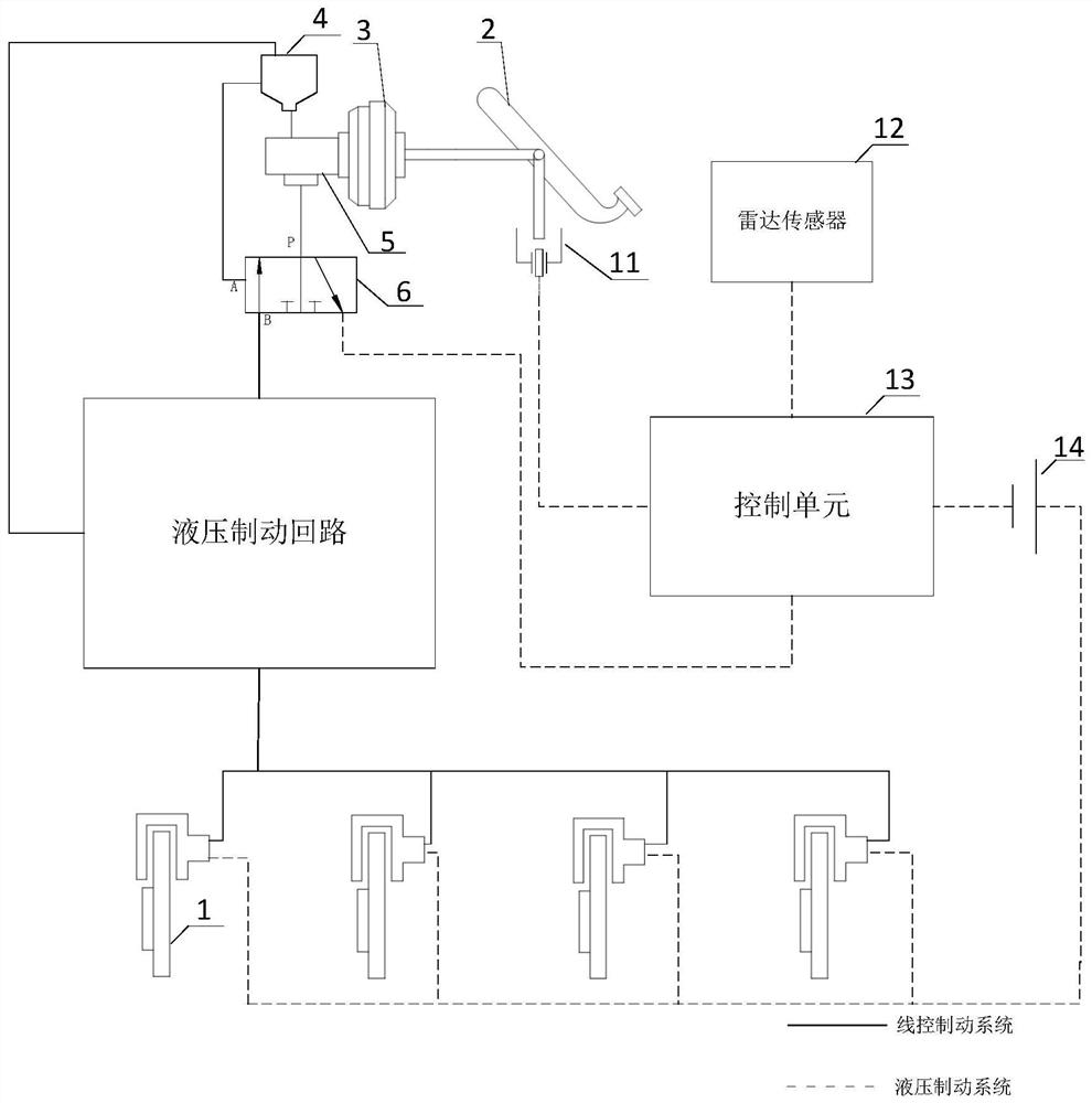
[0047] Such as Figure 8 As shown, the present invention is a structural schematic diagram of a fault-tolerant control system for automotive brake-by-wire failures, including the fault-tolerant control system as described in Embodiment 1, and its structure, working principle and working process have been described in Embodiment 1 , will not be described in detail here; the fault-tolerant control system in this embodiment also includes a radar sensor 12 connected with the control unit 13 signal, and the radar sensor 12 is installed on the self-driving car to sense the surrounding road conditions and judge whether it is necessary to control the vehicle. move.

[0048] The control method of the fault-tolerant control system in this embodiment includes the following steps:

[0049] Step 1, the radar sensor 12 judges whether braking is required according to the road surface information in front of the vehicle;

[0050] Step 2, when the brake-by-wire system is normal, the radar se...


PUM


Abstract

The invention discloses a fault-tolerant control system and a control method for automobile brake-by-wire failures, including a brake-by-wire system and a hydraulic brake system; For self-driving cars, it receives the radar sensor signal) and controls the brake to work; at this time, the control unit also controls the two-position three-way solenoid valve to make the oil in the master cylinder of the hydraulic braking system pass through the two-position three-way solenoid valve under the action of the brake pedal. The three-way solenoid valve flows back to the liquid storage tank and does not drive the brake to work. When the brake-by-wire system breaks down, the control unit controls the brake-by-wire system to stop working, and controls the two-position three-way solenoid valve to connect the master cylinder of the hydraulic brake system with the wheel cylinder. At this time, the vehicle uses the hydraulic brake system to achieve braking. verb: move. The invention can satisfy the driver's braking demand when the automobile's brake-by-wire brake fails, realizes the coordinated control of the automobile's wire-by-wire brake system and the hydraulic brake system, and improves the safety of the vehicle.

Description

technical field [0001] The invention belongs to the technical field of automobiles, and in particular relates to a fault-tolerant control system and a control method aiming at the failure of automobile brake-by-wire failures. Background technique [0002] The braking performance of a car is one of the main performances of a car. The braking performance is directly related to traffic safety. Some major traffic accidents are often caused by the poor braking performance of the car, too long braking distance, and sideways accidents during emergency braking. slippery and other reasons. With the continuous development of the automobile industry and the continuous increase in the number of automobiles, safety has become the primary factor considered by the majority of car owners when purchasing a car, and people are paying more and more attention to the braking performance of automobiles. [0003] The traditional automobile hydraulic braking system is mainly composed of brake peda...

Claims


Application Information

Patent Timeline
Patent Type & Authority Patents(China)
IPC IPC(8): B60T13/58B60T13/74
CPCB60T13/58B60T13/741B60T2270/402B60T2270/404
Inventor 陈龙陈智星徐兴仵晓涵王峰
Owner JIANGSU UNIV
Why Eureka
Try Eureka