
Fan blade

A technology of fan blades and fan blade seats, which is applied to components of pumping devices for elastic fluids, non-variable pumps, machines/engines, etc., and can solve the problems of difficult screwing of seat cores, low safety performance, and potential safety hazards and other problems, to achieve the effect of simple disassembly and high safety performance

Inactive Publication Date: 2011-06-01
NINGBO APG APPLIANCE & TECH CO LTD
View PDF5 Cites 1 Cited by
  • Summary
  • Abstract
  • Description
  • Claims
  • Application Information

AI Technical Summary

Problems solved by technology

However, in the process of screwing, it is difficult to screw the seat core of the fan blade seat and the output shaft of the motor in place, so that it is difficult to screw the seat core of the fan seat seat on the output shaft of the motor, and the fan blade is easily dislodged from the output shaft of the motor. falling off the shaft, posing a safety hazard
If the seat core of the fan blade seat is completely screwed on the output shaft of the motor, when the user needs to disassemble the fan blade, it will be difficult to remove the fan blade
[0003] To sum up, using the above structure to fix the fan blade seat on the output shaft of the motor for electric fans or ventilation fans has the disadvantages of low safety performance and inconvenient installation and disassembly.

Method used


Image

  • Fan blade
  • Fan blade
  • Fan blade

Examples


Embodiment Construction

[0032] The present invention will be further described below in conjunction with the accompanying drawings and specific embodiments.

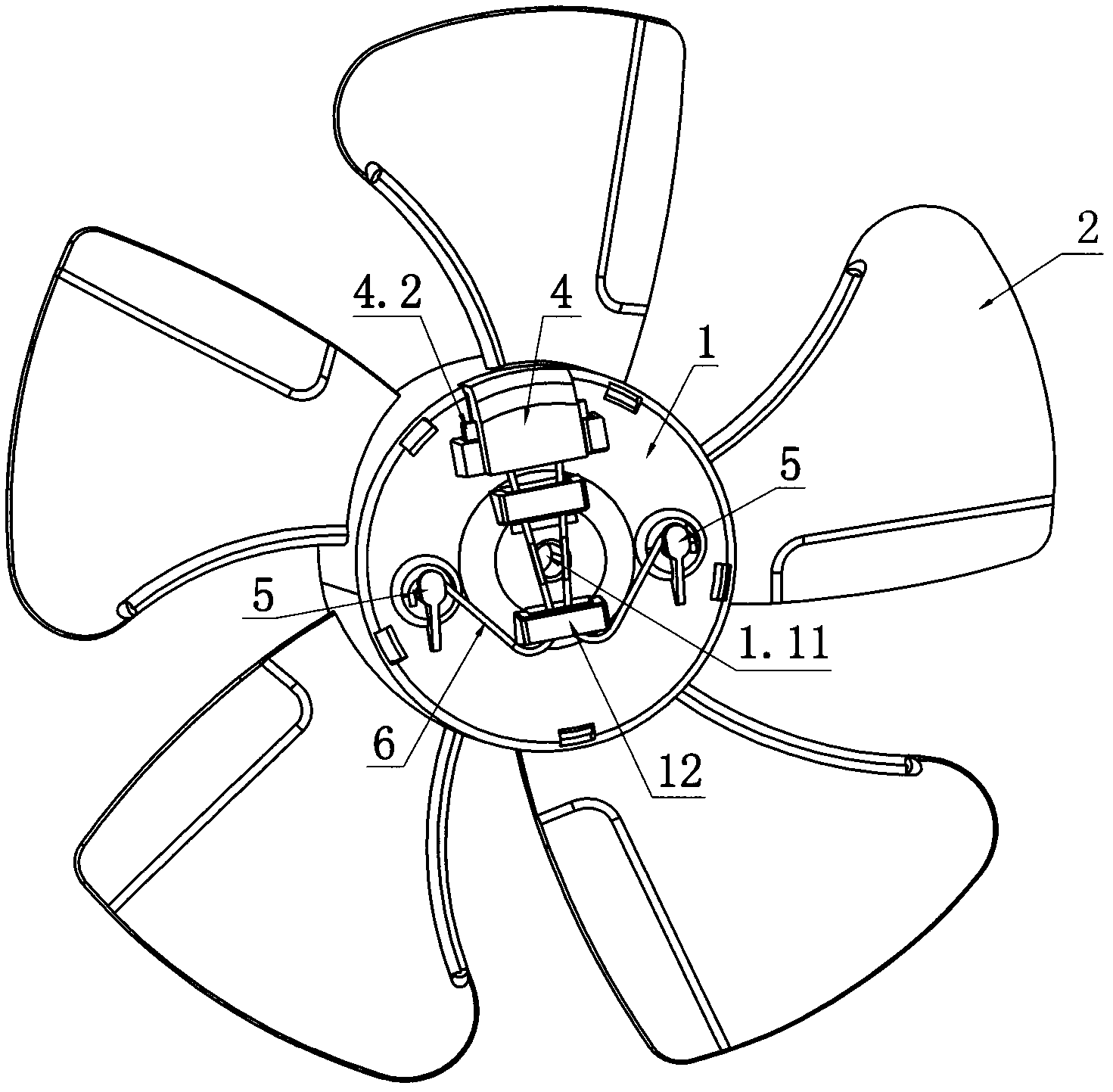
[0033] Such as Figure 1 to Figure 8 As shown, the fan blade of the present invention includes a fan blade seat 1 at the center, a blade 2 arranged on the edge of the fan blade seat 1 and integrated with the fan blade seat 1, and a fan blade installed on the fan blade seat 1 Seat cover 3. A seat core 1.1 is provided inside the fan blade seat 1, and an axial through hole 1.11 is provided on the seat core 1.1 for the output shaft of the motor to be inserted into. The fan blade also includes a fixing device that can fix the fan blade on the output shaft of the motor, and the fixing device is arranged on the fan blade seat 1 .

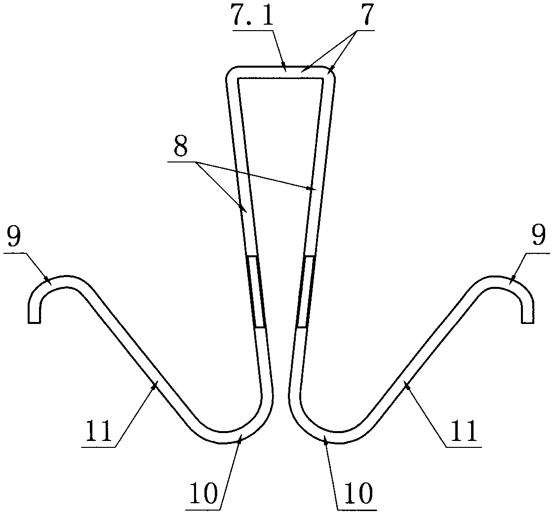
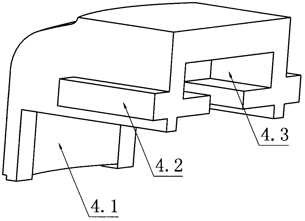
[0034] The fixing device includes a push block 4 , a limiting post 5 and a connecting clip 6 . In order to realize that the push block 4 is movably arranged on the fan blade seat 1, the edge of the fan blade seat 1 is pr...


PUM


Abstract

The invention discloses a fan blade comprising a fan blade seat (1). The fan blade (1) is internally provided with a seat core (1.1), and an axial through hole (1.11) for the insertion of an output shaft of a motor is arranged on the seat core (1.1). The fan blade further comprises a fixing device capable of fixing blades on the output shaft of the motor, and the fixing device is arranged on the fan blade seat (1). The invention has the advantages that the fan blade is conveniently fixed on the output shaft of the motor, is conveniently detached and has high safety.

Description

Technical field: [0001] The invention relates to a fan blade used on an electric fan or a ventilation fan. Background technique: [0002] The blades of the electric fan or ventilating fan generally include a blade seat at the center, blades arranged on the edge of the blade seat and integrally connected with the blade seat, and an end cover of the blade seat installed on the blade seat. At present, the fan blade is generally fixed to the output shaft of the motor by the following structure, that is, a seat core with internal threads is provided on the fan blade seat of the fan blade, and a seat core matching the internal thread of the seat core is provided on the output shaft of the motor. external thread. When the user needs to fix the fan blade on the output shaft of the motor, it is sufficient to screw the seat core of the fan blade seat onto the output shaft of the motor. However, in the process of screwing, it is difficult to screw the seat core of the fan blade seat ...

Claims


Application Information

Patent Timeline
IPC IPC(8): F04D29/32F04D29/38
Inventor 罗国定
Owner NINGBO APG APPLIANCE & TECH CO LTD
Learn More