

Spindle motor and disc driving device
A spindle motor and axial technology, applied in the direction of electromechanical devices, electric components, synchronous motors with stationary armatures and rotating magnets, etc., can solve the problem of bending of magnetic components, cost increase of spindle motors, and edge displacement of magnetic components Positioning and other problems, to achieve the effect of suppressing the increase in the number of parts
- Summary
- Abstract
- Description
- Claims
- Application Information
AI Technical Summary
Problems solved by technology
Method used
Image

Examples
Embodiment Construction
[0024] Hereinafter, exemplary embodiments of the present invention will be described with reference to the drawings. Hereinafter, the shape and positional relationship of each member will be described with the direction along the central axis as the vertical direction and the direction in which the substantially cup-shaped housing portion of the base member opens as the upward direction. However, this defines the up-and-down direction for convenience of description, and does not limit the postures of the spindle motor and the disk drive device in use according to the present invention.
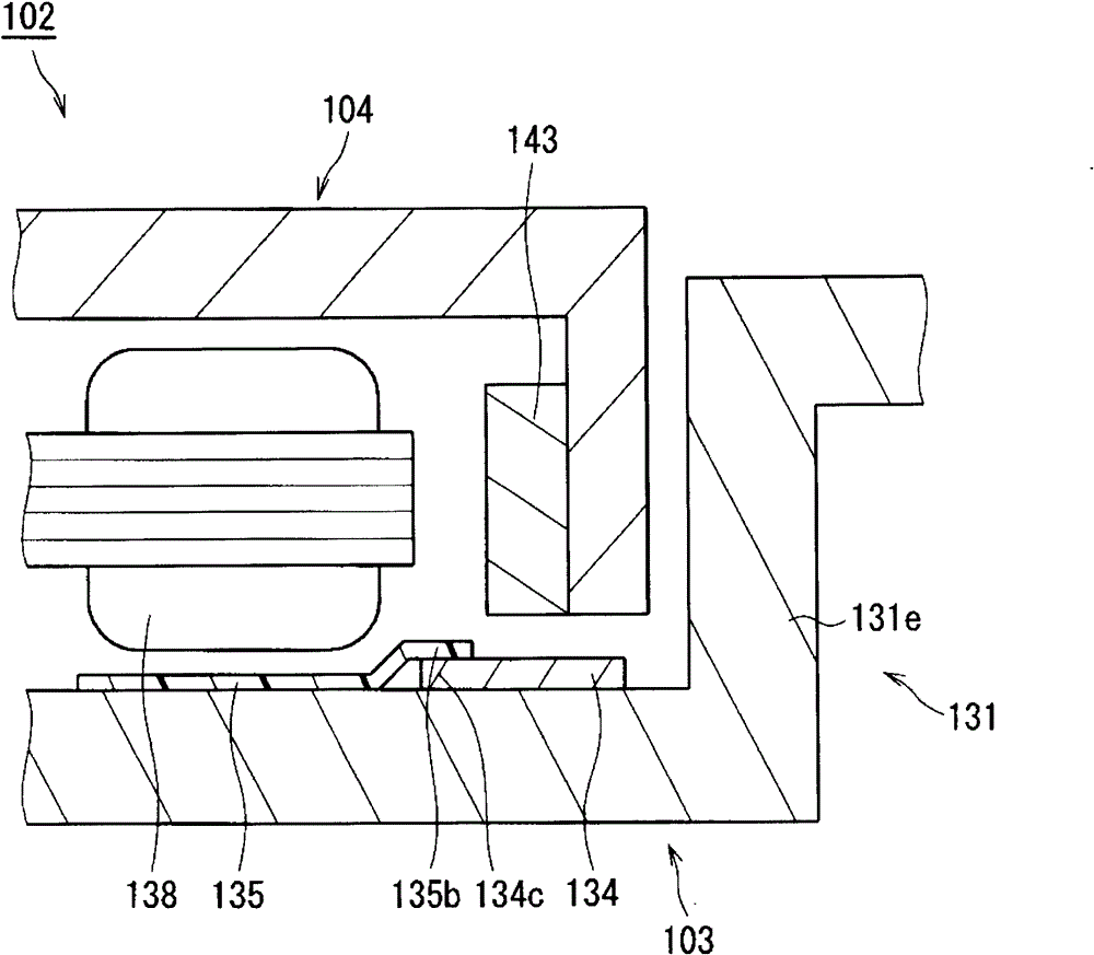
[0025] figure 1 It is a partial longitudinal sectional view of the spindle motor 102 according to one embodiment of the present invention. Such as figure 1 As shown, the spindle motor 102 has a stationary part 103 and a rotating part 104 . The rotating part 104 is rotatably supported with respect to the stationary part 103 .
[0026] The rotating part 104 has a magnet 143 . On the other h...
PUM
 Abstract
Description
Claims
Application Information