Castable Furnace Structure of a Cylindrical Rotary Heat Equipment

A furnace body structure and castable technology, which is applied in the field of cylindrical rotary heat equipment, can solve the problems of inability to quickly repair in a small area, lack of overall strength of the kiln lining, and low utilization rate of thermal efficiency, so as to prevent movement and displacement, The effect of increasing residence time and improving thermal efficiency utilization

Active Publication Date: 2015-08-19
洛阳市洛华粉体工程特种耐火材料有限公司
View PDF6 Cites 0 Cited by
  • Summary
  • Abstract
  • Description
  • Claims
  • Application Information

AI Technical Summary

Problems solved by technology

[0003] In order to solve the problems of low utilization rate of thermal efficiency, short service life and high maintenance cost of cylindrical rotary heating equipment in the prior art, the present invention creates a castable furnace body structure of cylindrical rotary heating equipment, which uses modern industrial furnace Kiln construction technology builds a high-efficiency, energy-saving integral kiln lining with a service life of several years, which effectively overcomes the slippage caused by the separation of the kiln lining and the separation of the steel shell during the operation of the traditional brick kiln lining, the kiln lining has no overall strength, and has instant relaxation and disintegration. , Inability to quickly repair in a small area and other defects, the cylindrical thermal equipment kiln lining has undergone subversive changes in terms of structure, materials, construction technology, maintenance and repair technology, so that the service life of the cylindrical kiln lining is longer than that of the brick kiln lining The improvement has been doubled to several times. The internal working cavity of the kiln lining can be changed arbitrarily according to the process requirements. The damage to a certain part of the kiln lining will not affect the life of the entire kiln body, and rapid and small-scale maintenance can be realized.

Method used


Image

  • Castable Furnace Structure of a Cylindrical Rotary Heat Equipment
  • Castable Furnace Structure of a Cylindrical Rotary Heat Equipment

Examples


Embodiment Construction

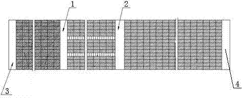
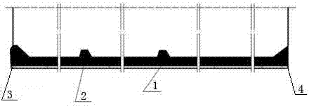
[0027] As shown in the figure, the castable furnace body structure of a cylindrical rotary heat equipment divides the furnace body into three areas: the low-temperature feed section, the high-temperature thermal reaction section, and the outlet orifice. The low-temperature feed section and the high-temperature thermal reaction section A retaining ring is set at the boundaries of the three areas of the section and the outlet orifice, and the retaining ring protrudes from the kiln lining, so that when the material enters a different temperature zone, the material retaining ring protrudes to the blocking function to make the material turn over and change the running track; The material retaining ring completes different functions according to different temperature sections of the thermal equipment: the material retaining ring set at the boundary between the low temperature section and the high temperature section is the high temperature boundary material retaining ring 1, from the ...


PUM


Abstract

Disclosed is a castable kiln structure of cylindrical heat rotary equipment. The castable kiln structure is characterized in that a kiln body is divided into a low-temperature feeding region, a high-temperature heat reaction region and an outlet and flow port. Retaining rings are arranged on regional boundaries of the low-temperature feeding region, the high-temperature heat reaction region and the outlet and flow port. The retaining rings protrude out of a kiln liner, so that the materials are enabled to turn over and change operation orbits through the retaining function of the protrusion height of the retaining rings when materials enter different temperature regions. The shortcomings that the kiln liner shaking during operation of a traditional bricked kiln liner to be separated from a steel casing to produce slip frequency with the same is free of overall strength, the kiln liner can be loosened and disintegrated instantly and cannot be maintained rapidly in a small range, and the like are effectively overcome, so that service life of the cylindrical kiln liner is prolonged by one to several times as compared with that of the bricked kiln liner, working cavities inside the kiln liner can be optionally changed according to technological requirements, damages to certain parts of the kiln liner do not cause affect to the service life of the whole kiln, and rapid maintenance in the small range can be achieved.

Description

technical field [0001] The invention relates to a large cylindrical rotary heat equipment, in particular to a castable furnace body structure of the cylindrical rotary heat equipment. Background technique [0002] In the heating field of various industries, it is widely used in the rotary heating equipment with kiln lining installed inside the cylindrical steel shell, also known as rotary kiln, rotary dryer, rotary roasting furnace, rotary calciner and so on. The furnace body of cylindrical rotary heat equipment is generally composed of an outer steel shell wrapped with a furnace lining to form a working area. The cylindrical rotary heat equipment is divided into temperature sections according to functions. When working, the kiln body rotates at a constant speed in one direction with a certain inclination. The low-temperature material is added from the tail of the heating equipment, and the head of the heating equipment is equipped with a flame spray gun to spray fire into...

Claims


Application Information

Patent Timeline
Patent Type & Authority Patents(China)
IPC IPC(8): F27D1/00
Inventor 李朝侠黄河
Owner 洛阳市洛华粉体工程特种耐火材料有限公司
Why Eureka
Try Eureka