Method, system and device for distributing contention resources

A technology of competing resources and allocation methods, applied in electrical components, wireless communication, etc., can solve the problem of how UE obtains competing resources without a corresponding technical solution, affecting applications, etc., and achieves the effect of satisfying the system state transition delay

Active Publication Date: 2011-06-08
DATANG MOBILE COMM EQUIP CO LTD
View PDF3 Cites 76 Cited by
  • Summary
  • Abstract
  • Description
  • Claims
  • Application Information

AI Technical Summary

Problems solved by technology

[0020] The disadvantage of the existing technology is that although the contention-based transmission method is proposed in the prior art, there is no corresponding

Method used


Image

  • Method, system and device for distributing contention resources
  • Method, system and device for distributing contention resources
  • Method, system and device for distributing contention resources

Examples


Embodiment 1

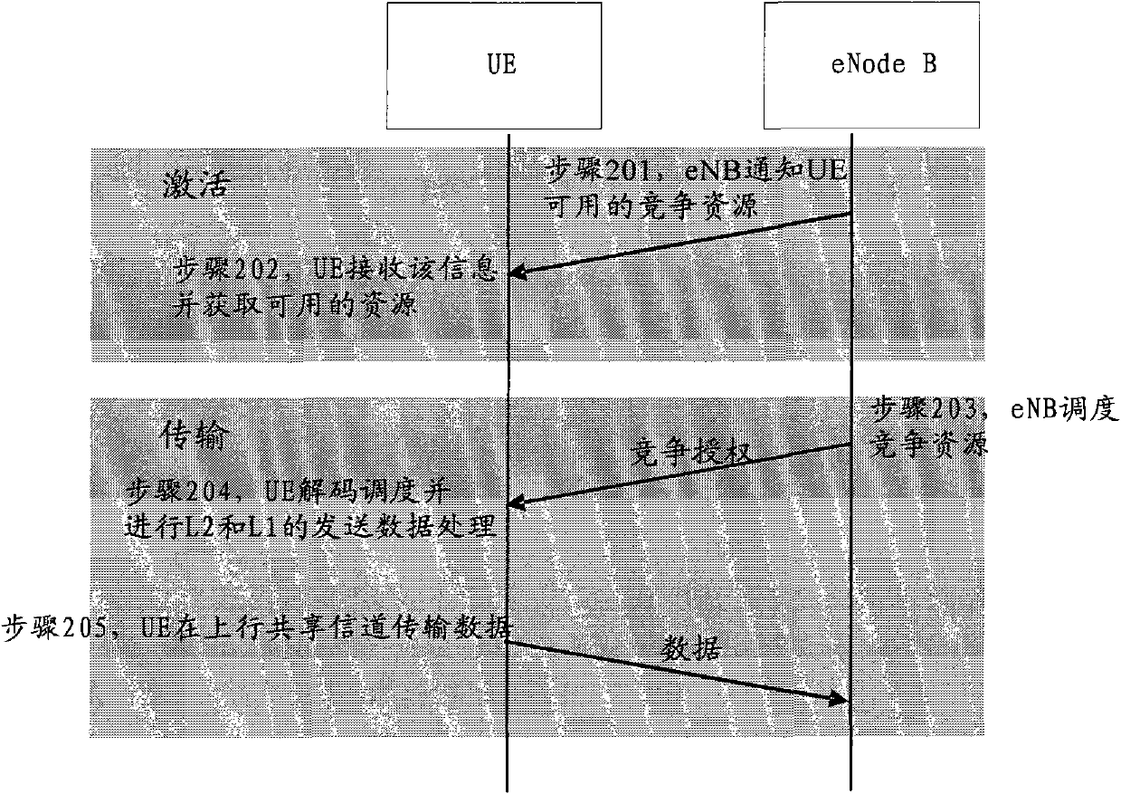
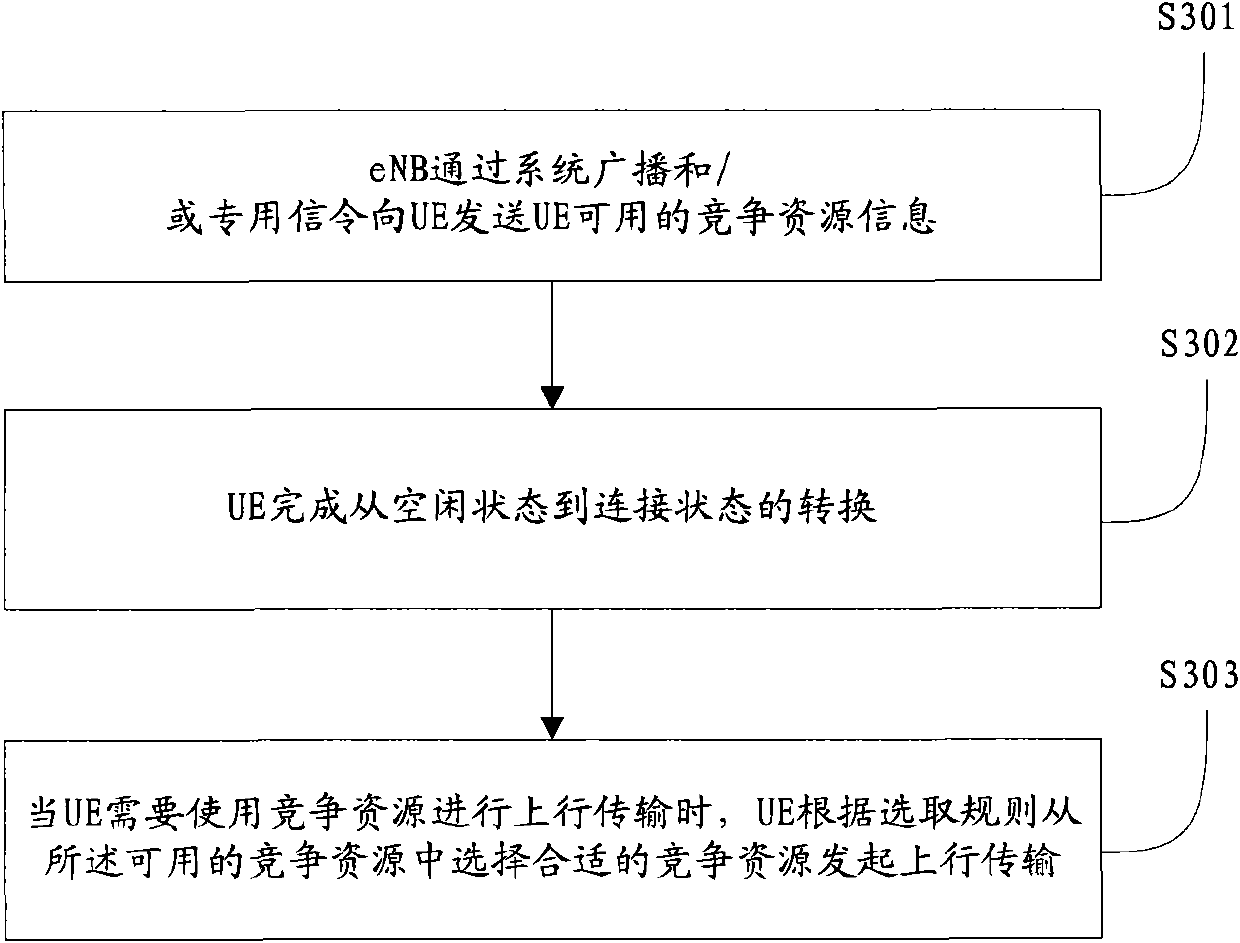
[0062] In this embodiment, a set of indicators can be specified, which can be used to indicate information such as different physical resource block frequency domain and time domain positions and their corresponding modulation and coding methods, and the network side publishes the available two Block contention resources and their corresponding indications, such as m and n, the steps for UE to use contention resources are as follows Figure 4 shown.

[0063] In step S401, the UE reads system broadcast information, and obtains information identifiers m and n related to contention resources therefrom.

[0064] In step S402, the UE completes the transition from the idle state to the connected state.

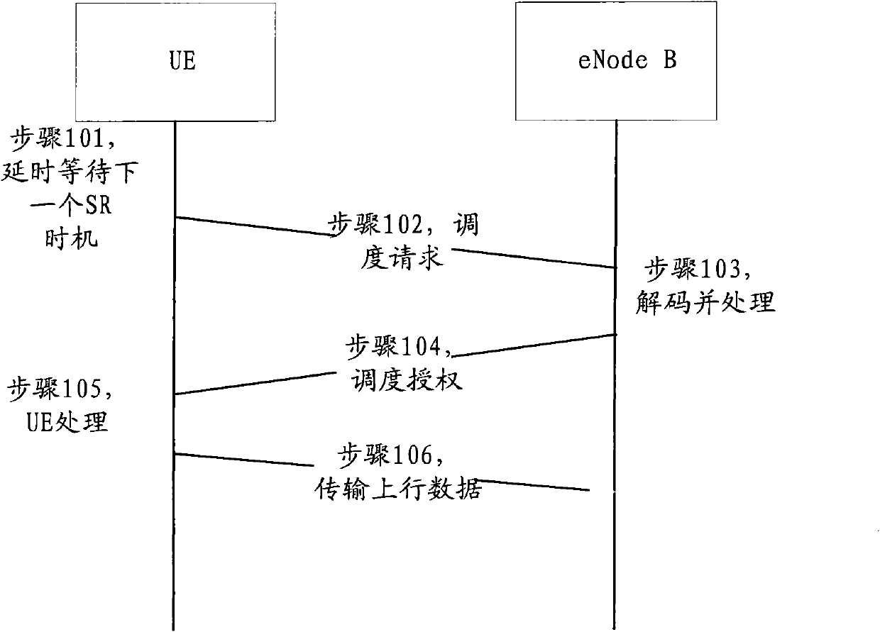
[0065] Step S403, the UE is in the synchronized state. When the UE needs to use contention resources for uplink transmission, such as meeting the sending Scheduling Request (SR) conditions or other situations where there is uplink data but no uplink resources are available for a pe...

Embodiment 2

[0068] In this embodiment, CB-RNTI is the default. The number of available CB-RNTI broadcast by eNB in ​​the system information is 2, and the default CB-RNTI is the first two or last two of the reserved parts (FFF4-FFFD) in the current RNTI value, or other specified methods Obtain. As shown in Table 1, the distribution of RNTI values ​​in R8 is as follows:

[0069] Table 1

[0070] value

RNTI

0000

N / A

0001-003C

RA-RNTI, C-RNTI, C-RNTI for semi-persistent scheduling, temporary

C-RNTI, TPC-PUCCH-RNTI and TPC-PUSCH-RNTI

003D-FFF3

C-RNTI, C-RNTI for semi-persistent scheduling, temporary C-RNTI,

TPC-PUCCH-RNTI and TPC-PUSCH-RNTI

FFF4-FFFD

reserve

[0071] FFFE

P-RNTI

FFFF

SI-RNTI

[0072] Such as Figure 5 As shown, it is a flow chart of UE initiating contention transmission in Embodiment 2, including the following steps:

[0073] In step S501, the UE reads the broad...

Embodiment 3

[0077] In this embodiment, the contention resource information also includes CB-RNTI grouping information, and the UE first selects a monitoring group according to its own situation, and then further selects a suitable contention resource from the selected group to initiate uplink transmission. The number of available CB-RNTIs broadcast by the eNB in ​​the system information is 3, of which the number of CB-RNTIs belonging to group A is 2, and the remaining 1 CB-RNTI is group B. The specific CB-RNTIs corresponding to each The value can be directly broadcast by the system information, or selected in the reserved area of ​​the RNTI space according to the default method, or other methods defined by the standard. Such as Figure 6 As shown, it is a flow chart of UE initiating contention transmission in Embodiment 3, including the following steps:

[0078] In step S601, the UE reads the broadcast information, obtains information about contention resources, obtains the currently ava...


PUM


Abstract

The invention provides a method for distributing contention resources. The method comprises the following steps that: user equipment (UE) receives contention resource information which is available for the UE and sent by an evolution node base (eNB) through a system broadcast and/or special signaling; and when needing to perform uplink transmission by using the contention resources, the UE selects a proper contention resource from the available contention resources according to a selection rule to perform the uplink transmission. By the embodiment, the eNB can send the contention resource information of the contention resources to the UE through the system broadcast and/or special signaling, so the UE can select the proper one from the contention resource information to perform the uplink transmission; and finally, the contention-resource-based transmission can be realized, and an aim of state switchover time delay of a long term evolution-access system is achieved.

Description

technical field [0001] The present invention relates to the field of communication technology, in particular to a method, system and device for allocating competitive resources. Background technique [0002] In the LTE (Long Term Evolution) system, a UE (User Equipment) in a dormant state (Dormant) has an RRC (Radio Resource Control, Radio Resource Control) connection with an eNB (Evolved Base Station) and an established radio bearer. However, DRX (discontinuous reception) is activated for the purpose of power saving, and it is currently in a temporary inactive state. Such as figure 1 As shown, it is a state transition flow chart under the LTE system in the prior art. The figure takes the state transition triggered by the uplink data of the UE in the synchronous state as an example, and includes the following steps: [0003] In step S101, the UE delays waiting for the next SR (Scheduling Request, scheduling request) opportunity. [0004] In step S102, the UE sends a sche...

Claims


Application Information

Patent Timeline
IPC IPC(8): H04W72/04H04W72/12
Inventor 刘佳敏赵亚利许芳丽
Owner DATANG MOBILE COMM EQUIP CO LTD
Why Eureka
Try Eureka