
Camshaft adjuster

A technology of camshaft adjuster and crankshaft drive, which is applied in the direction of machines/engines, valve devices, mechanical equipment, etc., and can solve the problems of increased leakage loss and increased clearance of camshaft adjusters

Active Publication Date: 2013-06-19
SCHAEFFLER TECH AG & CO KG
View PDF7 Cites 0 Cited by
  • Summary
  • Abstract
  • Description
  • Claims
  • Application Information

AI Technical Summary

Problems solved by technology

Experience has shown that despite the highest manufacturing precision, under the influence of elastic deformations, there is still the risk in the screw connection that the gap between the rotor, the wings and the screwed-on sealing cover increases and that As a result, internal leakage losses in the camshaft adjuster increase

Method used


Image

  • Camshaft adjuster
  • Camshaft adjuster
  • Camshaft adjuster

Examples


Embodiment Construction

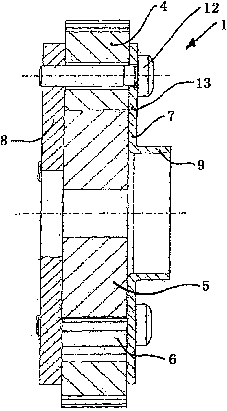
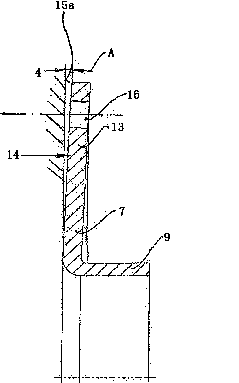
[0014] from figure 1 A camshaft adjuster 1 can be seen in the figure, which has a stator 4 which is driven by a crankshaft (not shown) of the internal combustion engine and a rotor 5 which is connected in a rotationally fixed manner to the camshaft. A plurality of working chambers 6 are arranged between the stator 4 and the rotor 5 and are delimited laterally by sealing covers 7 and sealing washers 8 . The working chamber 6 is formed by radially inwardly protruding projections of the stator 4 which are supported on the radial inner diameter of the rotor 5 . The working chamber 6 is divided into two working chambers 6 , for example by vanes assigned to the rotor 5 , to which pressure medium can be applied, so that the relative rotational position of the rotor 5 relative to the stator 4 can be changed and thus also the The relative rotational position of the camshaft relative to the crankshaft. The sealing cover 7 is firmly connected to the stator 4 by means of a plurality of ...


PUM


Abstract

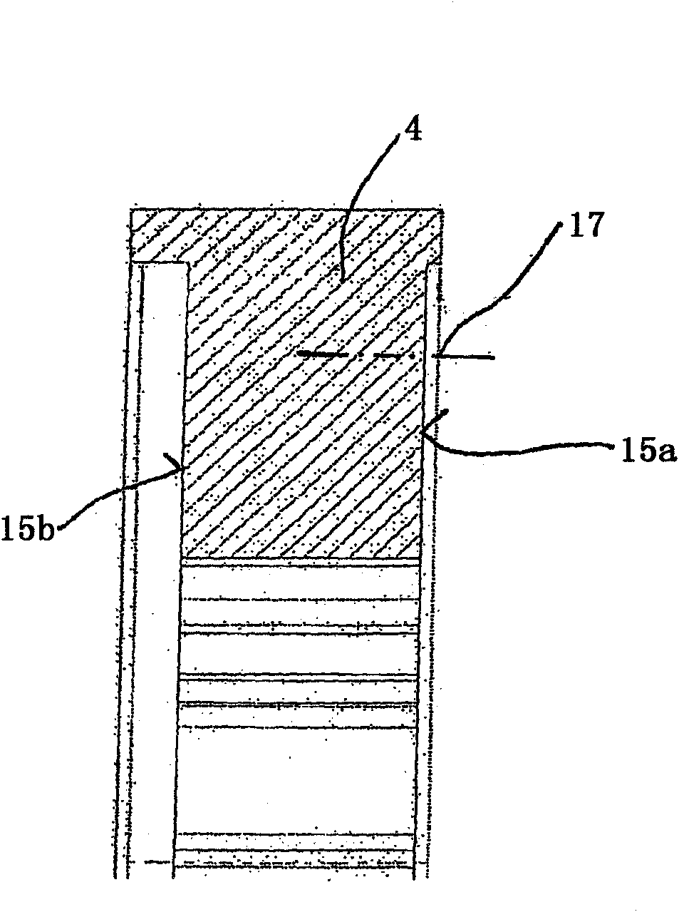
A camshaft adjuster for an internal combustion engine of a motor vehicle, including a stator which can be driven by a crankshaft of an internal combustion engine and is located radially on the outside, a rotor which is non-rotatably connected to a camshaft and located radially on the inside, working chambers which are disposed between the rotor and stator and can be subjected to a pressure such that the rotational position of the rotor relative to the stator can be varied, and at least one sealing cover which laterally delimits the working chambers and rests against the stator and / or rotor. The sealing cover, stator and / or rotor have a convex, concave or conical contact surface, and the sealing cover can be elastically deformed by the attachment via the contact surface such that it rests against the stator and / or rotor with an increased sealing force as a result of elastic deformation.

Description

technical field [0001] The invention relates to a camshaft adjuster having the features of the preamble of claim 1 . Background technique [0002] From DE 10 2005 020 529 A1 a camshaft adjuster according to the classification is known, which has a sealing cover, referred to there as a side arm (Seitenschenkel), which has a basic body in the form of an annular washer, which is passed through The screw connection is connected to the stator and bears sealingly against the rotor of the camshaft adjuster. The sealing cap has an annular washer-shaped base body which merges at its radially inner end into an axially cylindrical projection. Experience has shown that despite the highest manufacturing precision, under the influence of elastic deformations, there is still the risk in the screw connection that the gap between the rotor, the wings and the screwed-on sealing cover increases and that As a result, internal leakage losses in the camshaft adjuster increase. Contents of the...

Claims


Application Information

Patent Timeline
Patent Type & Authority Patents(China)
IPC IPC(8): F01L1/344
CPCF01L1/3442Y10T29/49293F01L1/46F01L1/047
Inventor 于尔根·韦伯马库斯·科贝尔
Owner SCHAEFFLER TECH AG & CO KG
Learn More