Anti-offset servo motor and using method thereof

A servo motor and anti-offset technology, applied in the field of servo motors, can solve problems such as output shaft wear, loose fixing screws, and motor output shaft offset, and achieve the effect of reducing wear and reducing the probability of screw loosening

Active Publication Date: 2019-12-20
HUNAN VOCATIONAL INST OF TECH
View PDF5 Cites 0 Cited by
  • Summary
  • Abstract
  • Description
  • Claims
  • Application Information

AI Technical Summary

Problems solved by technology

[0003] The servo motors currently used are fixed on the motor fixing frame first, and then the motor fixing frame is fixed on the machine. The servo motor and the motor fixing frame are fixed by fixing screws. The vibration of the machine makes the fixing screws used to fix the servo motor exist. Looseness will cause the servo motor and the motor fixing frame to vibrate. Long-term operation will cause the output shaft of the motor to shift. If the stability of the output shaft is not high, it is easy to shift during the rotation process. Any slight shift It will cause the parts of the output shaft to wear and affect the normal use and service life of the servo motor

Method used


Image

  • Anti-offset servo motor and using method thereof
  • Anti-offset servo motor and using method thereof
  • Anti-offset servo motor and using method thereof

Examples


Embodiment 1

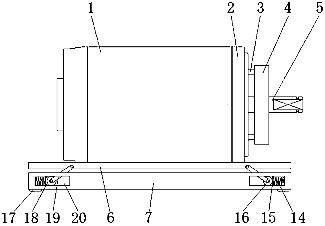
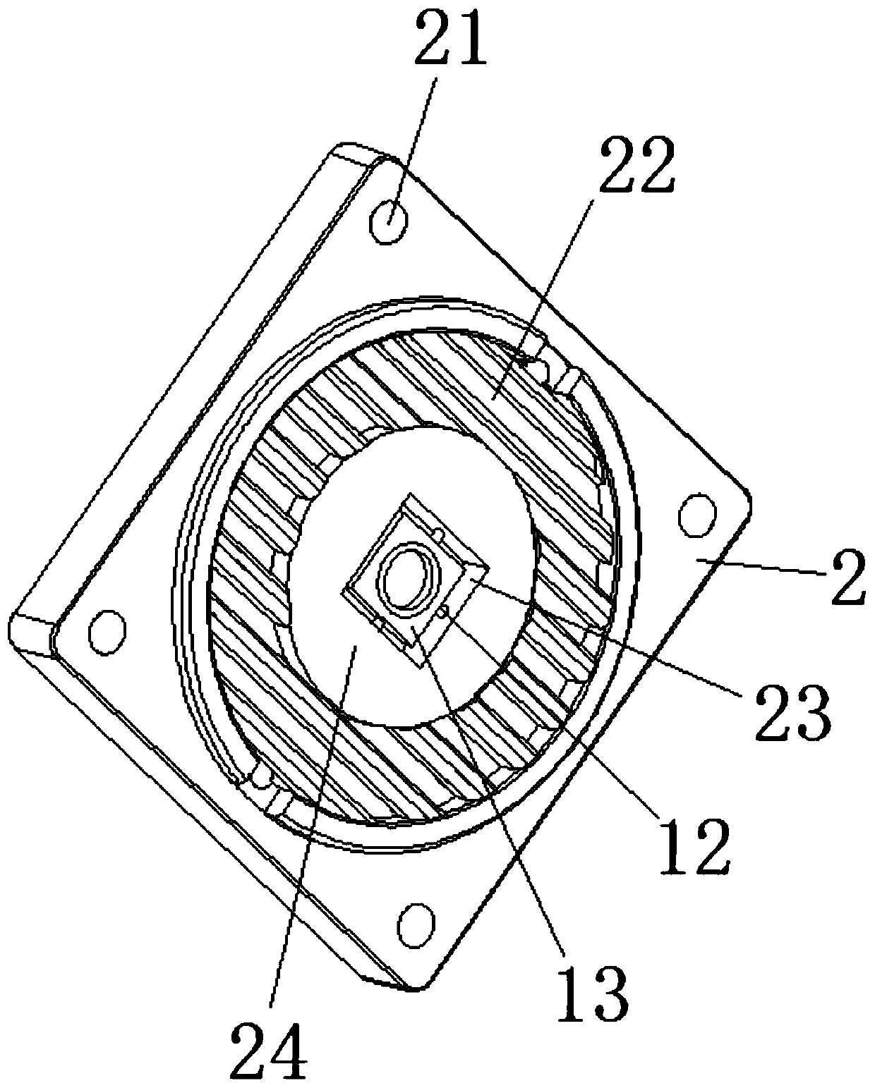
[0027] Example 1: Please refer to figure 1 , figure 2 , an anti-offset servo motor and its use method, comprising a servo motor 1 and a front end cover 2 on its front end, and a mounting base 6 on the bottom surface, and also includes an output shaft 5 of the servo motor 1, the front end cover 2 is integrated It is formed into a rectangular structure in section, and the four corners of the surface of the front end cover 2 are provided with installation holes 21 for screws to be installed on the front end of the servo motor 1, and the surface of the front end cover 2 is formed with a plurality of heat dissipation grooves 22 arranged side by side at equal distances To form a circular heat dissipation area, and the centers of the plurality of heat dissipation grooves 22 are fixedly connected with a support part 24, and a bearing seat 13 is arranged in the support part 24, and the output shaft 5 is positioned and fitted through the bearing seat 13, ensuring that the output shaft ...

Embodiment 2

[0030] Example 2: Please refer to figure 1 , image 3 , this embodiment adds the following technical features on the basis of Embodiment 1:

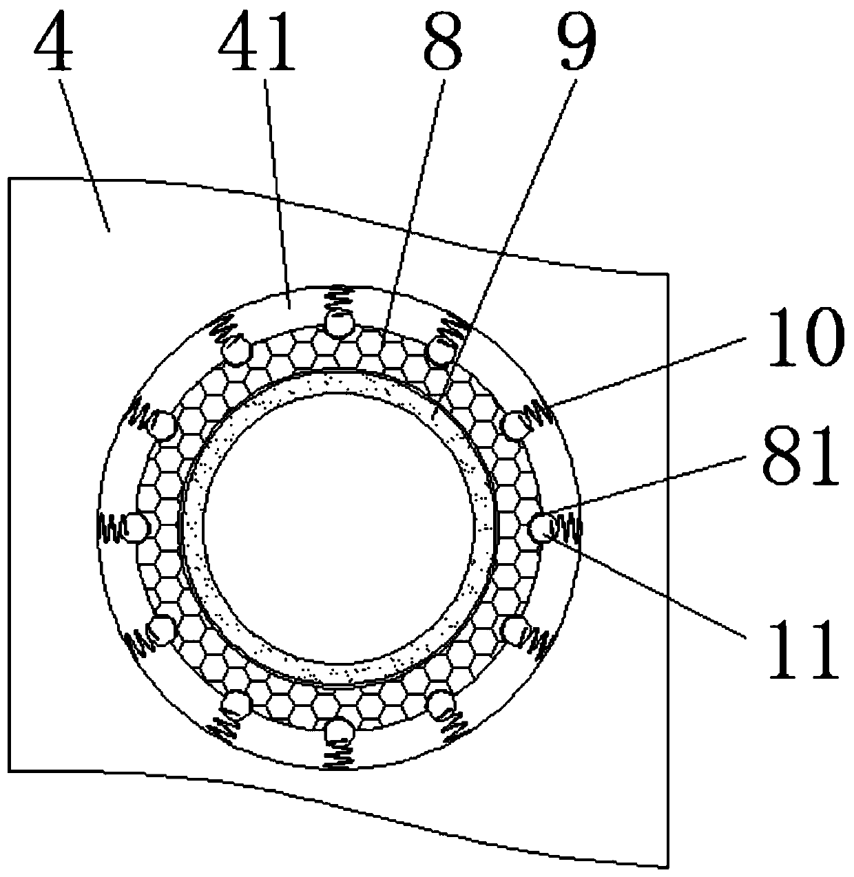
[0031] The output shaft 5 is provided with a compensation mechanism, a plurality of symmetrical installation rods 3 fixedly connected to the outer surface of the front end cover 2, and the end of the installation rod 3 away from the front end cover 2 is fixedly connected to the limit plate 4, and the surface of the limit plate 4 A perforation 41 is opened in the middle, and a limit ring 9 is connected to the perforation 41 through a compensation mechanism. The limit ring 9 is used for passing through the output shaft 5 , and the limit ring 9 and the output shaft 5 are arranged coaxially and do not touch each other.

[0032] Further, the compensation mechanism includes one end of a plurality of springs 10 fixedly connected to the peripheral surface of the perforation 41, and the other ends of the plurality of springs 10 are all facing th...

Embodiment 3

[0034] Example 3: Please refer to figure 1 , this embodiment adds the following technical features on the basis of Embodiment 1 or Embodiment 2:

[0035] The mounting base 6 of the servo motor 1 is connected to a bottom plate 7 through a shock absorbing mechanism, the shock absorbing mechanism includes a cavity 20 formed at the four corners inside the bottom plate 7, and both sides of the bottom plate 7 are symmetrically connected to one end of a buffer rod 19, four buffers The rod 19 deviates from the central axis of the bottom plate 7 and is arranged obliquely downward, and the other end of the buffer rod 19 passes through the through groove on the upper surface of the bottom plate 7 to the corresponding cavity 20 and is hinged with a roller 16, which rolls in contact with the upper and lower surfaces of the cavity 20 , and the end face of the cavity 20 is connected to one end of the compression spring 14, the other end of the compression spring 14 is connected to one side o...


PUM


Abstract

The present invention discloses an anti-offset servo motor and a using method thereof, and relates to the technical field of servo motors. The anti-offset servo motor comprises a servo motor, a frontcover on the front surface of the servo motor, a mounting base on the bottom surface of the servo motor, and an output shaft of the servo motor; the surface of the front cover is provided with a plurality of equally spaced heat dissipation slots arranged in parallel to form a circular heat dissipation area; a support portion is fixedly connected to the center of the plurality of heat dissipation slots; a bearing seat is arranged inside the support portion; and a compensation mechanism is arranged on the output shaft. According to the technical scheme of the present invention, fixed installation for the output shaft is realized through the bearing seat, and the anti-offset effect of the output shaft can be achieved while ensuring that the output shaft rotates unimpededly; the compensation mechanism plays a buffer role when the output shaft is offset, wear of the output shaft is reduced, and the force can be re-fed back to the output shaft in time to restore a normal rotation state of the output shaft; and by using a damping mechanism, the probability of loosening the screws on the servo motor after long-term operation can be greatly reduced, so that the damping mechanism indirectlyplays a role in preventing the output shaft from being offset.

Description

technical field [0001] The invention relates to the technical field of servo motors, in particular to an anti-offset servo motor and a use method thereof. Background technique [0002] Servo motor refers to the engine that controls the operation of mechanical components in the servo system. It is an auxiliary motor indirect transmission device. The servo motor can control the speed and position accuracy very accurately. It can convert the voltage signal into torque and speed to drive the control object. , the rotor speed of the servo motor is controlled by the input signal, and can respond quickly. In the automatic control system, it is used as an actuator, and has the characteristics of small electromechanical time constant, high linearity, and starting voltage. The signal is converted into angular displacement or angular velocity output on the motor shaft. It is divided into two categories: DC and AC servo motors. Its main feature is that there is no self-rotation phenomen...

Claims


Application Information

Patent Timeline
IPC IPC(8): H02K5/24H02K7/00
CPCH02K5/24H02K7/003
Inventor 陈揆能
Owner HUNAN VOCATIONAL INST OF TECH
Why Eureka
Try Eureka