Rotary compressor

A technology of rotating compressors and sliders, applied in the field of compressors, can solve problems such as energy loss, inability to prevent high-pressure gas, and reduction in the volume of suction chambers, and achieve the effect of reducing suction efficiency.

Active Publication Date: 2011-06-15
PANASONIC WANBAO GUANGZHOU COMPRESSOR
View PDF7 Cites 2 Cited by
  • Summary
  • Abstract
  • Description
  • Claims
  • Application Information

AI Technical Summary

Problems solved by technology

Although the noise reduction effect is achieved, due to the need for the air column to oscillate back and forth, the air column all flows into the cylinder suction chamber during the return journey from the resonance chamber 23 to the cylinder 13. Because the high-pressure gas flows into the low-pressure chamber, this Part of the high-pressure gas expands and occupies part of the volume of the suction chamber of the cylinder, which reduces the volume of the suction chamber, reduces the suction efficiency of the compressor, and loses ener

Method used


Image

  • Rotary compressor
  • Rotary compressor
  • Rotary compressor

Examples


Embodiment 1

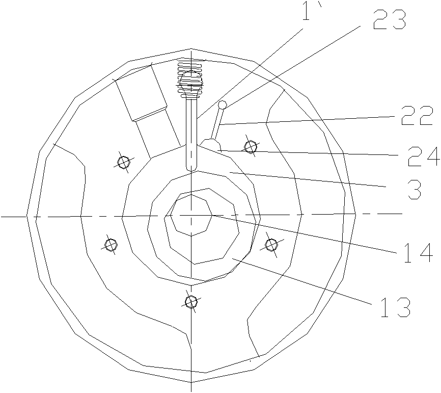
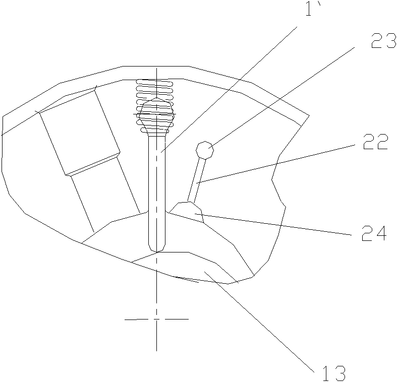
[0022] Such as Figure 4 As shown, the slider is composed of two sliders 20, 21 that can move relative to each other, and the communication passages 12 of the two sliders 20, 21 are arranged at corresponding positions, forming an exhaust cutout 24 and a resonance chamber 23 that can communicate with each other. The opening and closing of the resonance chamber are realized when the two sliders 20 and 21 are in different positions.

[0023] When the cylinder 3 compresses the gas, the two sliders 20, 21 move to a specific position, and when the opening of the communication passage 12 is connected (intersecting or overlapping) with the opening of the exhaust small groove 22, the exhaust notch 24 and the resonance cavity 23 are communicated. When inhaling, the communication channels 12 of the sliders 20 and 21 are closed by the side walls of the slider grooves to cut off the exhaust cutout 24 and the resonance chamber 23. The high-pressure gas column in the resonance chamber cannot...

Embodiment 2

[0029]In this embodiment, the cross-sectional area of ​​the communication channel 12 is larger than the opening of the small exhaust groove 22 on the side wall of the groove of the slider. By properly enlarging the communication channel 12 of the two sliders 20, 21, the range of the piston rotation angle for the exhaust notch 24 and the resonance cavity 23 to still be in communication can also be enlarged.

[0030] Other structures of this embodiment are the same as those of Embodiment 1.


PUM


Abstract

The invention discloses a rotary compressor. A compression component of the rotary compressor comprises a crankshaft, an air cylinder, an upper bearing, a lower bearing, a piston and a sliding block which moves along a sliding block groove, wherein an air exhaust cavity of the air cylinder is provided with a resonant chamber; the resonant chamber comprises an air exhaust cut and a resonant cavity between which the sliding block with a communicating channel is arranged; and a communicating state or an isolating state of the air exhaust cut and the resonant cavity is switched by the moving sliding block through the communicating channel. When the rotary compressor compresses air, a high-pressure air column in the air cylinder can enter the resonant chamber at a specific position; in the air sucking process, the high-pressure air column in the air cylinder cannot flow back, high-pressure air only can be permeated through a gap between the sliding block and the sliding block groove of the air cylinder, so that the problem that the air sucking efficiency of the conventional compressor is reduced is solved.

Description

technical field [0001] The invention relates to the field of compressors, in particular to a rotary compressor for air conditioners. Background technique [0002] Such as Figure 1~3 The hermetic rotary compressor shown generally requires a compression assembly and a motor assembly. The existing motor assembly includes a stator and a rotor. The existing compression assembly includes a crankshaft 14, a cylinder 3, an upper bearing 11, a lower bearing 15, a piston 13 and a slide Block 1`. The piston 13 and the slide block 1` in the compression assembly are installed inside the cylinder 3, and a rotating crankshaft 14 with an eccentric part is arranged inside the cylinder 3, and the upper and lower end surfaces of the cylinder 3 are closed by upper and lower bearings, so that a A cavity that can be off-centered. And, the refrigerant sucked in from the suction pipe is compressed in the compression chamber of the cylinder 3, and then the compressed refrigerant is discharged out...

Claims


Application Information

Patent Timeline
IPC IPC(8): F04C18/356
Inventor 高青山炊军立金林
Owner PANASONIC WANBAO GUANGZHOU COMPRESSOR
Why Eureka
Try Eureka