Structure for fixing magnetic poles of permanent magnet motor
A technology of fixed magnetic poles and permanent magnet motors, applied in the direction of magnetic circuit shape/style/structure, magnetic circuit rotating parts, etc., can solve the problems of unreliable positioning of rotor magnetic poles, and achieve easy implementation, improved processing efficiency, and simple structure Effect
- Summary
- Abstract
- Description
- Claims
- Application Information
AI Technical Summary
Problems solved by technology
Method used
Image
Examples
specific Embodiment approach 1
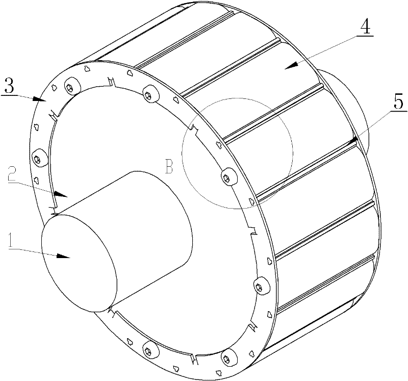
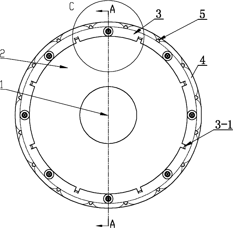
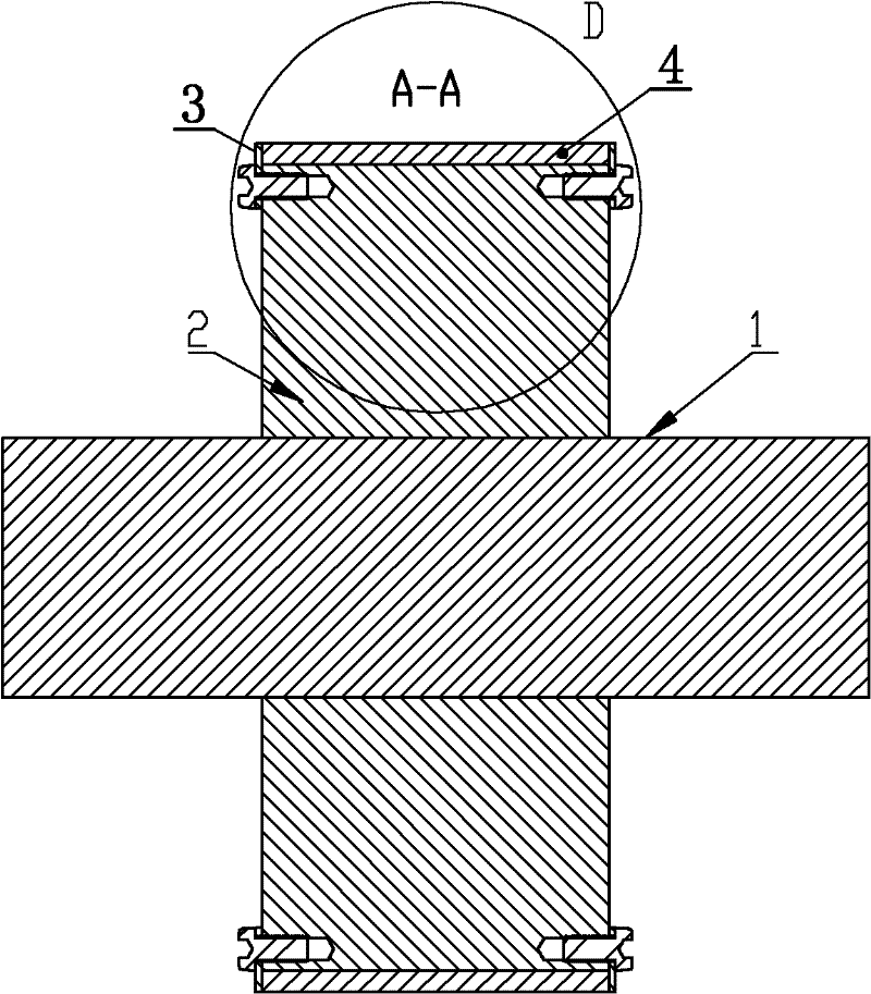
[0029] Specific implementation mode one: the following combination Figure 1 to Figure 6 To describe this embodiment,
[0030] This embodiment includes a rotating shaft 1 and a rotor yoke 2. The rotor yoke 2 is sleeved on the outer surface of the rotating shaft 1. It also includes two annular rotor pressure plates 3, P magnetic poles 4 and P positioning keys 5.
[0031] Two ring-shaped rotor pressure plates 3 are respectively fixedly connected to both ends of the rotor yoke 2, and form grooves with the outer surface of the rotor yoke 2. P positioning keys 5 are evenly distributed along the circumferential direction of the rotor, and the grooves are evenly divided. There are P accommodating spaces along the axial direction of the rotor, and one magnetic pole 4 is fixedly arranged in each accommodating space.
specific Embodiment approach 2
[0032] Specific implementation mode two: the following combination Figure 1 to Figure 9 Describe this embodiment, this embodiment is a further description of Embodiment 1,
[0033] A plurality of positioning pins 3-1 are stamped on each annular rotor pressure plate 3, and a positioning hole 2-1 is provided on the rotor yoke 2 corresponding to each positioning pin 3-1. The positioning pin 3-1 is tenon-jointed with the positioning hole 2-1 one by one; each annular rotor pressure plate 3 is fixedly connected with the rotor yoke 2 through a plurality of screws, and the plurality of screws are evenly distributed on the annular rotor pressure plate 3 , and spaced apart from the positioning pin 3-1.
[0034] Others are the same as the first embodiment.
[0035] In this embodiment, a plurality of positioning pins 3 - 1 are respectively embedded in a plurality of positioning holes 2 - 1 to realize the positioning of the annular rotor pressure plate 3 in the circumferential direction...
specific Embodiment approach 3
[0036] Specific implementation mode three: the following combination Figure 1 to Figure 9 Describe this embodiment, this embodiment is a further description of Embodiment 1 or 2,
[0037] P slots 3-2 are uniformly arranged on each annular rotor pressure plate 3, and each slot 3-2 is used to fix one end of a positioning key 5.
[0038] Others are the same as the first or second embodiment.
PUM
 Abstract
Description
Claims
Application Information
 - R&D
- Intellectual Property
- Life Sciences
- Materials
- Tech Scout
- Unparalleled Data Quality
- Higher Quality Content
- 60% Fewer Hallucinations
Browse by: Latest US Patents, China's latest patents, Technical Efficacy Thesaurus, Application Domain, Technology Topic, Popular Technical Reports.
© 2025 PatSnap. All rights reserved.Legal|Privacy policy|Modern Slavery Act Transparency Statement|Sitemap|About US| Contact US: help@patsnap.com


