Medical tube

一种医疗用管、医疗设备的技术,应用在医疗用管领域,能够解决操作性变差、操作性下降、难引导等问题,达到良好操作性、使用便利性好的效果

Inactive Publication Date: 2011-06-15
OLYMPUS CORP
View PDF8 Cites 8 Cited by
  • Summary
  • Abstract
  • Description
  • Claims
  • Application Information

AI Technical Summary

Problems solved by technology

[0009] When the periphery of the side hole 101a of the tubular member 101 is bent, in order to make the front end of the insertion portion 103 of the choledochoscope 102 point to the observation direction, the insertion portion 103 must be bent more. However, since the amount of bending of the insertion portion 103 is limited, There is a problem that it is difficult to accurately guide the tip of the insertion part 103 in the direction of observation, resulting in poor operability.
[0010] In order to cope with this situation, it is conceivable to increase the hardness around the side hole 101a of the tubular member 101 to make it difficult to bend. (For example, in the case of the duodenal bulb), it is difficult to bend the front end of the tubular member 101, which reduces the operability
[0011] Also, it is considered that after guiding the tubular member 101 to the duodenal papilla A etc. located in the viewing direction, for example, the wire-shaped hard member 52 disclosed in Japanese Patent Laying-Open No. 9-258441, or the Japanese The restricting body 10 disclosed in JP-A-11-76182 is inserted through a tubular member to increase rigidity. However, since the tubular member is bent in the body cavity, it is difficult to insert the rigid member or the restricting body orally into the near the tip of the tubular member

Method used


Image

  • Medical tube
  • Medical tube
  • Medical tube

Examples


Embodiment approach

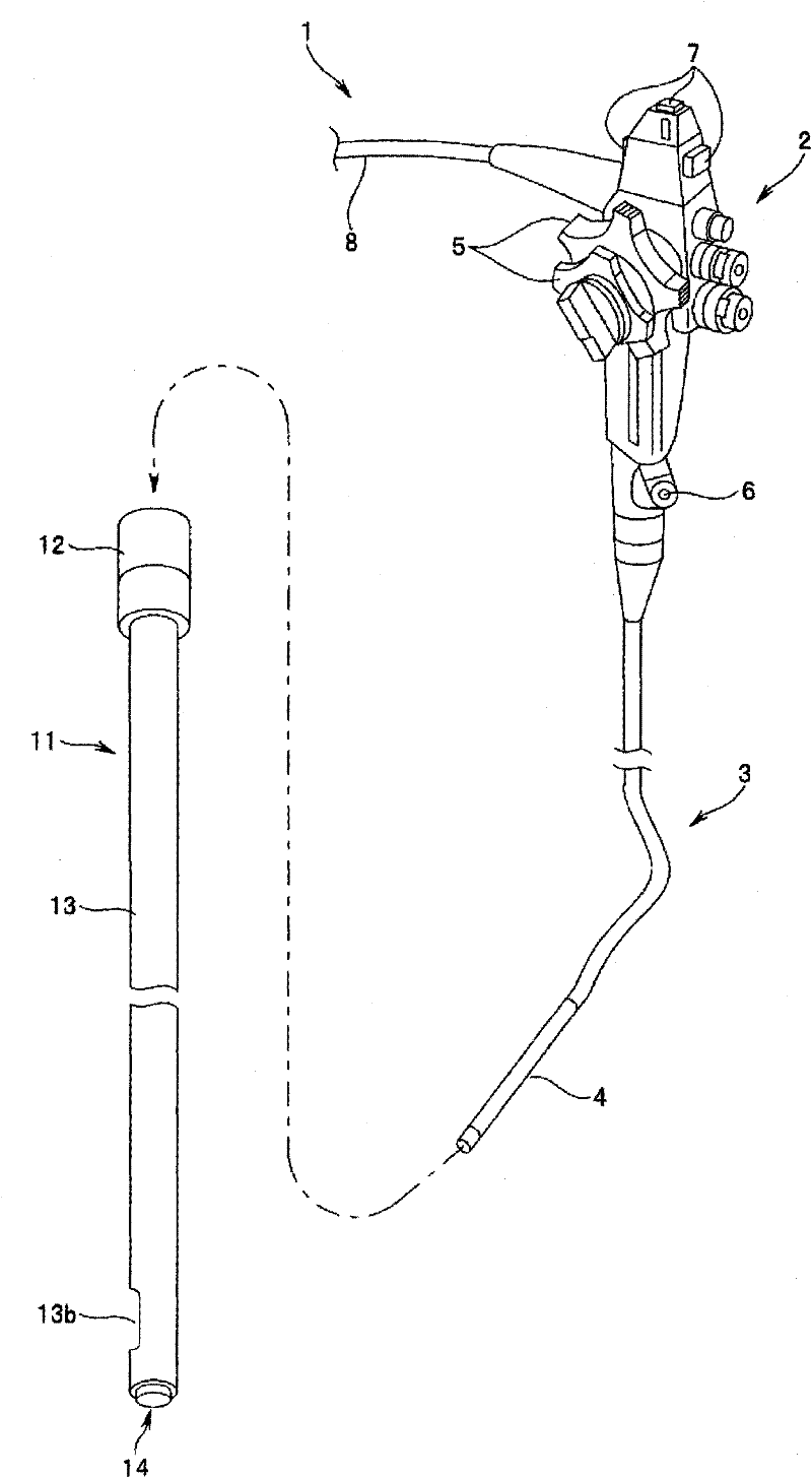
[0076] Reference numeral 1 in the figure is an endoscope as a representative medical device, and a choledochoscope is shown in this embodiment. Therefore, this endoscope 1 will be referred to as a choledochoscope 1 and described below.

[0077] The choledochoscope 1 has an operating part 2 on the proximal side, from which a flexible insertion part 3 extends. In addition, the operation part 2 is provided with a bending operation knob 5 for bending the bending part 4 provided at the front end part of the insertion part 3, and an insertion port 6 through which a treatment instrument is inserted through an insertion channel for inserting a treatment instrument or the like. A universal cord 8 is extended from the end of the operation part 2, and the universal cord 8 is connected to a light source device (not shown) to transmit illumination light and various signals, and the illumination light from the light source device passes through the universal cord 8 It is guided toward the ...

no. 2 approach

[0094] Figure 11 ~ Figure 16B A second embodiment of the present invention is shown. In addition, the same code|symbol is attached|subjected to the same component as 1st Embodiment, and description is abbreviate|omitted.

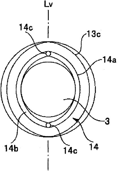
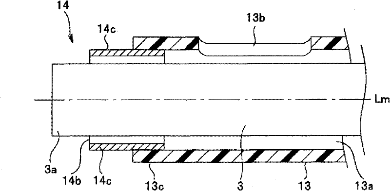
[0095] In the above-mentioned first embodiment, the spring mouth-shaped hardness changing part 14 is provided at the front end part 13c of the tube main body 13 provided on the medical tube 11, and the hardness changing part 14 makes the end of the tube main body 13 stretch from the front end to the pipeline. The part of the support portion P2 is elastically deformed, but in this embodiment, the small-diameter hardness changing portion is provided with a side wire 21, and by pulling the side wire 21, at least the area S of the pipe main body 13 (refer to Figure 3B ) Elastic deformation.

[0096] That is, if Figure 11 , Figure 12A As shown, the side wire 21 is disposed on the front end portion 13c of the tube body 13 of the medical tube 11 . Both end...

no. 3 approach

[0114] Figure 17 A perspective view of main parts showing a medical tube according to a third embodiment of the present invention. This embodiment is a modified example of the second embodiment described above. The pipe main body 13 used in this embodiment is a member used instead of the pipe main body 13 used in the above-mentioned second embodiment, and the structure of the rear end side of the pipe main body 13 is the same as that described above. Figure 13 , Figure 14 The configuration shown is the same. Therefore, using Figure 13 , Figure 14 The structure of the rear end side of the pipe main body 13 will be described. In addition, the same reference numerals will be assigned to the same components as those in the second embodiment and will be described.

[0115] In the second embodiment, the side wire 21 is connected to the front end portion 13c of the pipe main body 13, and the side wire 21 is pulled to elastically deform at least the front end portion 13c of...


PUM


Abstract

A medical tube provided with: a tube body (13) having a duct (13a) penetrating therethrough from the tip to the rear end thereof, the duct (13a) allowing the insertion section (3) of a cholangioscope (1) to be inserted therethrough; a side hole (13b) formed at a position between the tip and the rear end of the tube body (13) and interconnecting the outer peripheral side surface of the insertion section (3) and the duct (13a); and a hardness changing section (14) capable of changing, according to an operation by the operator, the hardness of at least that part of the tube body (13) which includes the side hole (13b).

Description

technical field [0001] The present invention relates to a medical tube for guiding medical equipment inserted into a body cavity. Background technique [0002] Generally, endoscopic duodenal papillotomy is used for non-invasive treatment of common bile duct stones. However, there are few cases of common bile duct stones complicated with intrahepatic stones, and sometimes it is necessary to undergo endoscopic duodenal papillatomy. The case of intrahepatic stones treated after papillotomy to remove common bile duct stones. Therefore, it is desired to be able to diagnose and treat intrahepatic calculi using oral cholangioscopy. [0003] However, in the case of an endoscope as a representative of medical equipment inserted from the stomach side, the outlet opening of the biliary tract is directed in the return direction with respect to the duodenum, so when you want to insert the endoscope into the biliary tract In the case of the endoscope, it is necessary to bend the front e...

Claims


Application Information

Patent Timeline
Patent Type & Authority Applications(China)
IPC IPC(8): A61B1/00
CPCA61B1/005A61M25/007A61B1/00154A61M25/0074A61B1/00078A61B1/273A61M2025/0681A61B1/0125A61B1/2736A61B1/00135A61B1/00098
Inventor 本田一树仓康人松浦航
Owner OLYMPUS CORP
Why Eureka
Try Eureka