

Insulating coating composition and an insulated wire, and a coil formed using the same
a technology of insulating coating and insulating wire, which is applied in the direction of plastic/resin/waxes insulators, textiles and paper, transportation and packaging, etc., can solve the problems that the effect of improving the low varnish adhesion strength within the conventional practice cannot be enough to prevent the reduction of the varnish adhesion strength, and the effect of improving the lubricity of the insulating coating
- Summary
- Abstract
- Description
- Claims
- Application Information
AI Technical Summary
Benefits of technology
Problems solved by technology
Method used
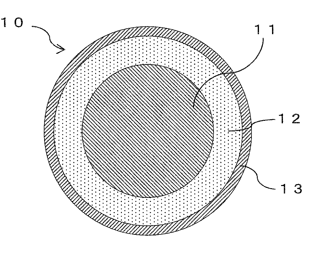
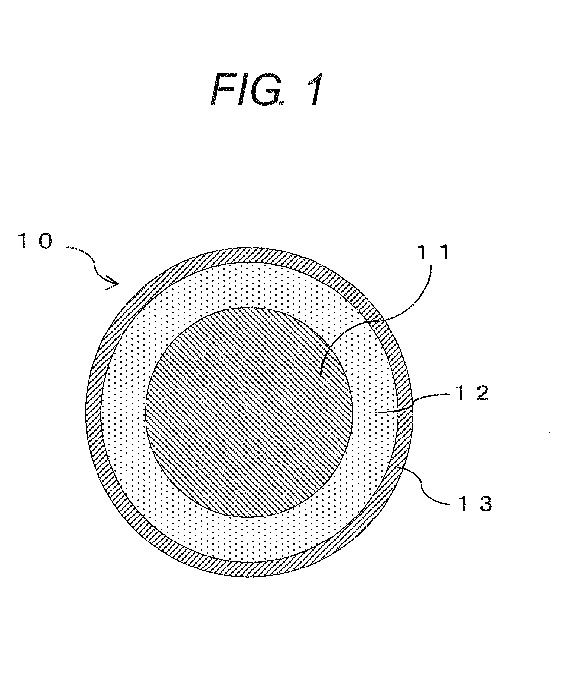
Image

Examples
embodiment examples
[0043]Embodiment examples and comparison examples are prepared and examined as follows.
[0044]Raw materials listed in the descriptions for the embodiment examples and the comparison examples given below were charged in a flask provided with an agitator, a reflux cooling tube, a nitrogen gas supplying tube, and a thermometer. Charged raw materials were agitated in nitrogen atmosphere being heated to reach 140° C. in about one hour and allowed to react with each other for two hours at that temperature. On completion of the two-hour reaction, the reaction was terminated using a blocking agent listed in the descriptions for the embodiment examples and the comparison examples so that a solution of the polyamide-imide resin having a reduced viscosity of about 0.4 dl / g would be obtained. Thus, the polyamide-imide resin to be used as the base resin for coating composition is obtained.
[0045]And then, into the 100 parts by mass of the polyamide-imide resin, lubricant component, additives, and ...
embodiment example 1
[0051]MDI (4,4′-diphenylmethane diisocyanate) of 255.0 g (1.02 mol) as the isocyanate component, trimellitic anhydride (TMA) of 192.0 g (1.0 mol) as the acid component, and NMP (N-methyl-2-pyrrolidone) of 1100 g as the solvent were charged and allowed to proceed to a synthetic reaction. Then, oleyl alcohol (carbon number: C18) of 5.4 g (0.02 mol) was charged as the blocking agent to cease the synthetic reaction. Thus, the polyamide-imide resin having 28 mass % of resin concentration was obtained.
[0052]Further, polyolefin series lubricant of 8.9 g (2 parts by mass) was dispersed therein as the lubricant to obtain the self-lubricating polyamide-imide resin insulating coating composition.
embodiment example 2
[0053]MDI of 255.0 g (1.02 mol) as the isocyanate component, TMA of 192.0 g (1.0 mol) as the acid component, and NMP of 1100 g as the solvent were charged and allowed to proceed to a synthetic reaction. Then, oleyl alcohol of 13.4 g (0.05 mol) was charged as the blocking agent to cease the synthetic reaction. Thus, the polyamide-imide resin having 28 mass % of resin concentration was obtained.
[0054]Further, polyolefin series lubricant of 8.9 g (2 parts by mass) was dispersed therein as the lubricant to obtain the self-lubricating polyamide-imide resin insulating coating composition.
PUM
| Property | Measurement | Unit |
|---|---|---|
| Diameter | aaaaa | aaaaa |
| Diameter | aaaaa | aaaaa |
| Molar ratio | aaaaa | aaaaa |
Abstract
Description
Claims
Application Information