Card connector adapted for cards having different width dimensions

a card connector and card connector technology, applied in the direction of connectors, instruments, containers, etc., can solve the problems of not being able to handle those two cards, and the card connector cannot handle those cards having different width dimensions

Inactive Publication Date: 2007-11-27
JAPAN AVIATION ELECTRONICS IND LTD
View PDF10 Cites 3 Cited by
  • Summary
  • Abstract
  • Description
  • Claims
  • Application Information

AI Technical Summary

Benefits of technology

[0005]It is therefore an object of this invention to provide a card connector that can handle different kinds of cards having different width dimensions.
[0006]It is another object of this invention to provide a card connector having excellent insertability that can easily guide a card at the time of its insertion.

Problems solved by technology

There are, however, two kinds of express cards having different width dimensions and, therefore, it is not possible for a card connector to handle those two kinds of express cards if the card connector is simply applied with a technique of an existing card connector designed for connecting a PC card.
However, this card connector cannot handle those cards having different width dimensions like the express cards.

Method used


Image

  • Card connector adapted for cards having different width dimensions
  • Card connector adapted for cards having different width dimensions
  • Card connector adapted for cards having different width dimensions

Examples


Embodiment Construction

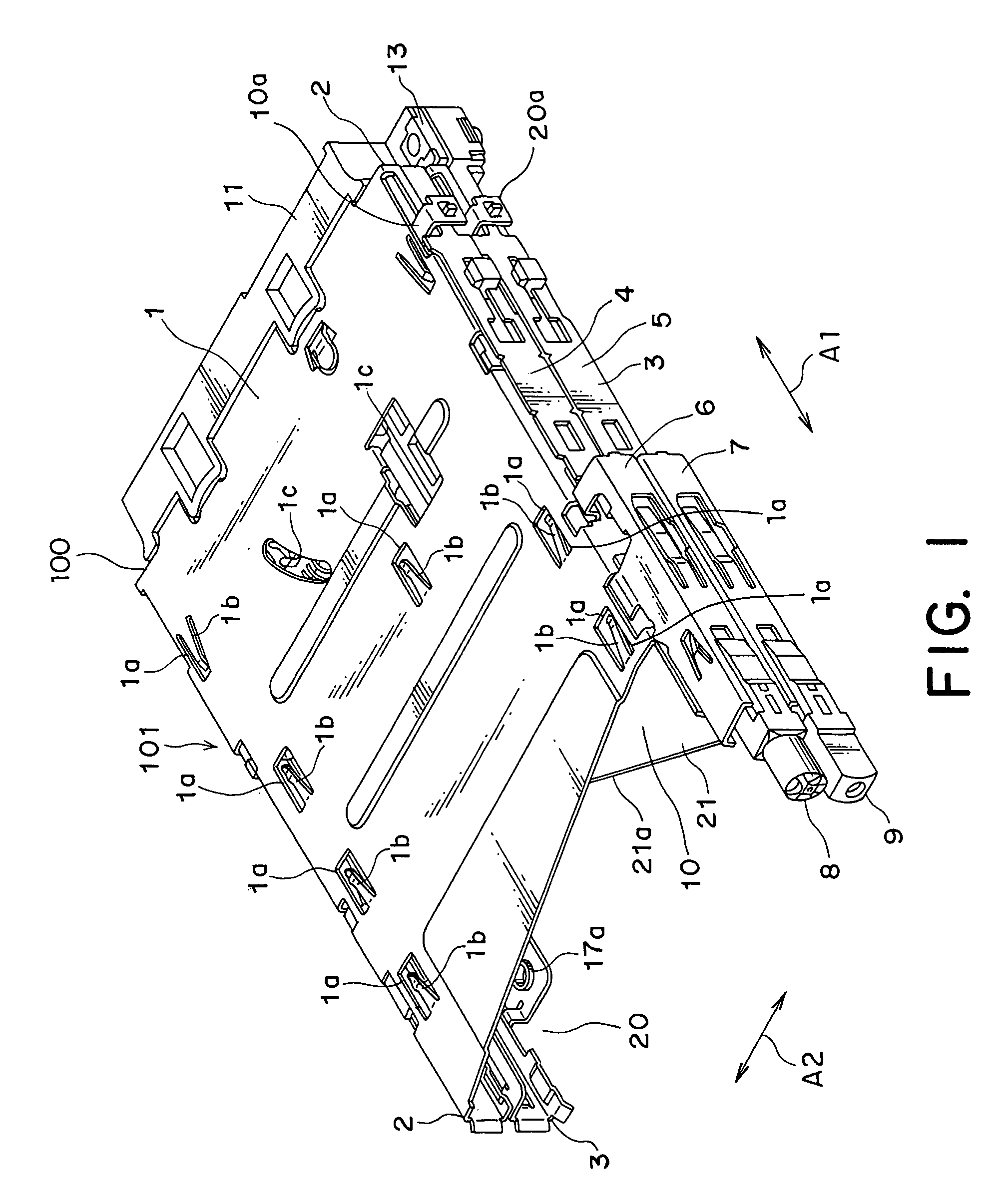
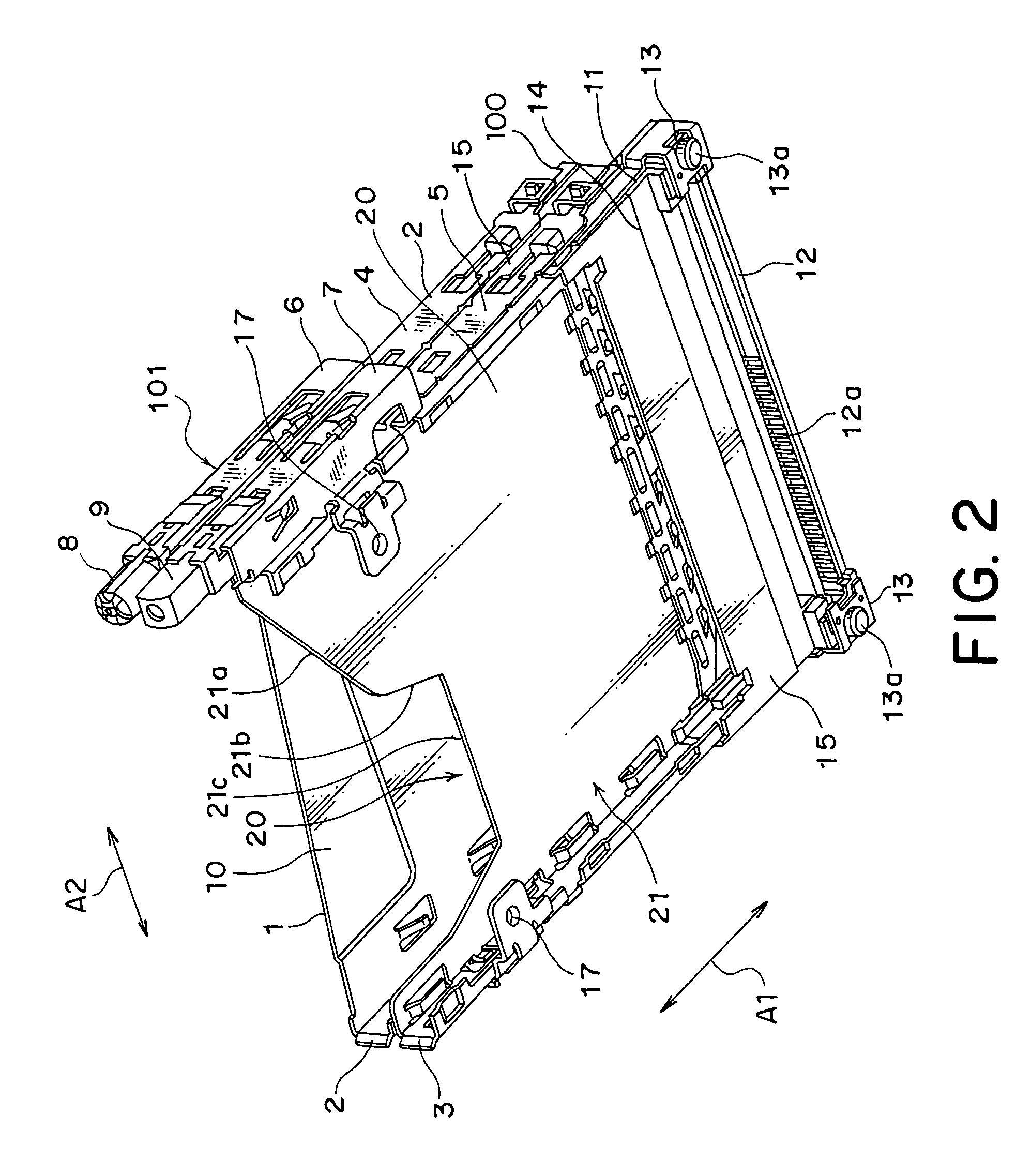
[0042]Referring to FIGS. 1, 2, and 3A to 3D, description will be made about a card connector according to an embodiment of this invention.

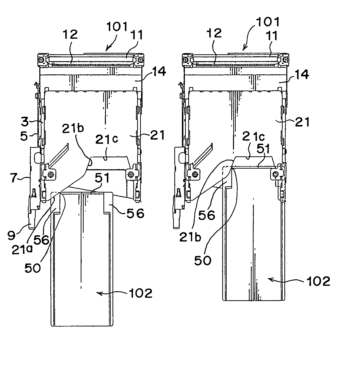
[0043]The card connector is depicted by reference numeral 101 and comprises a housing 100 forming an outer shell and a plate portion or a partition plate 21 fixed to the housing 100. The partition plate 21 extends in a first direction A1 and a second direction A2 perpendicular to the first direction A1 and forms a guide member having a guide portion adapted to guide insertion of a card being a connection object.

[0044]The card connector has multiple card slots. That is, the housing 100 has an inner space that is divided into an upper card slot 10 and a lower card slot 20 by the partition plate 21. The upper card slot 10 is for an express card, while the lower card slot 20 is for a PC card.

[0045]The housing 100 has, on its front side, entrances for receiving cards into the card slots 10 and 20, respectively. The housing 100 further has an insulator ...


PUM


Abstract

In a connector including a housing having an entrance for receiving a connection object and a contact held by the housing for connection to the connection object, a guide member is coupled to the entrance for guiding the connection object in a first direction. A guide portion is disposed near the entrance in the housing and at a first portion in a second direction perpendicular to the first direction. By the use of a moving force of the connection object, the guide portion is adapted to guide the connection object toward a second portion that allows the connection object to pass therethrough.

Description

[0001]This application claims priority to prior Japanese patent application JP 2005-56205, the disclosure of which is incorporated herein by reference.BACKGROUND OF THE INVENTION[0002]This invention relates to a card connector for connecting a card such as an express card or the like.[0003]Recently, cards called express cards having a function similar to that of PC cards have been proposed and available on the market. There are, however, two kinds of express cards having different width dimensions and, therefore, it is not possible for a card connector to handle those two kinds of express cards if the card connector is simply applied with a technique of an existing card connector designed for connecting a PC card.[0004]Japanese Unexamined Patent Application Publication (JP-A) No. 2000-67996, for example, discloses one example of a card connector that is used for loading and then ejecting a card such as a memory card. The card connector comprises a connector body having two panels de...

Claims


Application Information

Patent Timeline
Patent Type & Authority Patents(United States)
IPC IPC(8): H01R13/44
CPCG06F1/187H01R27/02G06K7/0043H01R12/71
Inventor KIMURA, AKIRAWADA, TAKAMITSU
Owner JAPAN AVIATION ELECTRONICS IND LTD
Why Eureka
Try Eureka