
Communication terminal position determination device

A technology of communication terminal and judging device, which is applied in the direction of selection device, telemetry/remote control selection device, transportation and packaging, etc.

Active Publication Date: 2013-11-06
KK TOKAI RIKA DENKI SEISAKUSHO
View PDF2 Cites 0 Cited by
  • Summary
  • Abstract
  • Description
  • Claims
  • Application Information

AI Technical Summary

Problems solved by technology

In addition, the problem is not limited to the electronic key system, but occurs in various systems that communicate between the two by wireless

Method used


Image

  • Communication terminal position determination device
  • Communication terminal position determination device
  • Communication terminal position determination device

Examples


no. 1 Embodiment approach

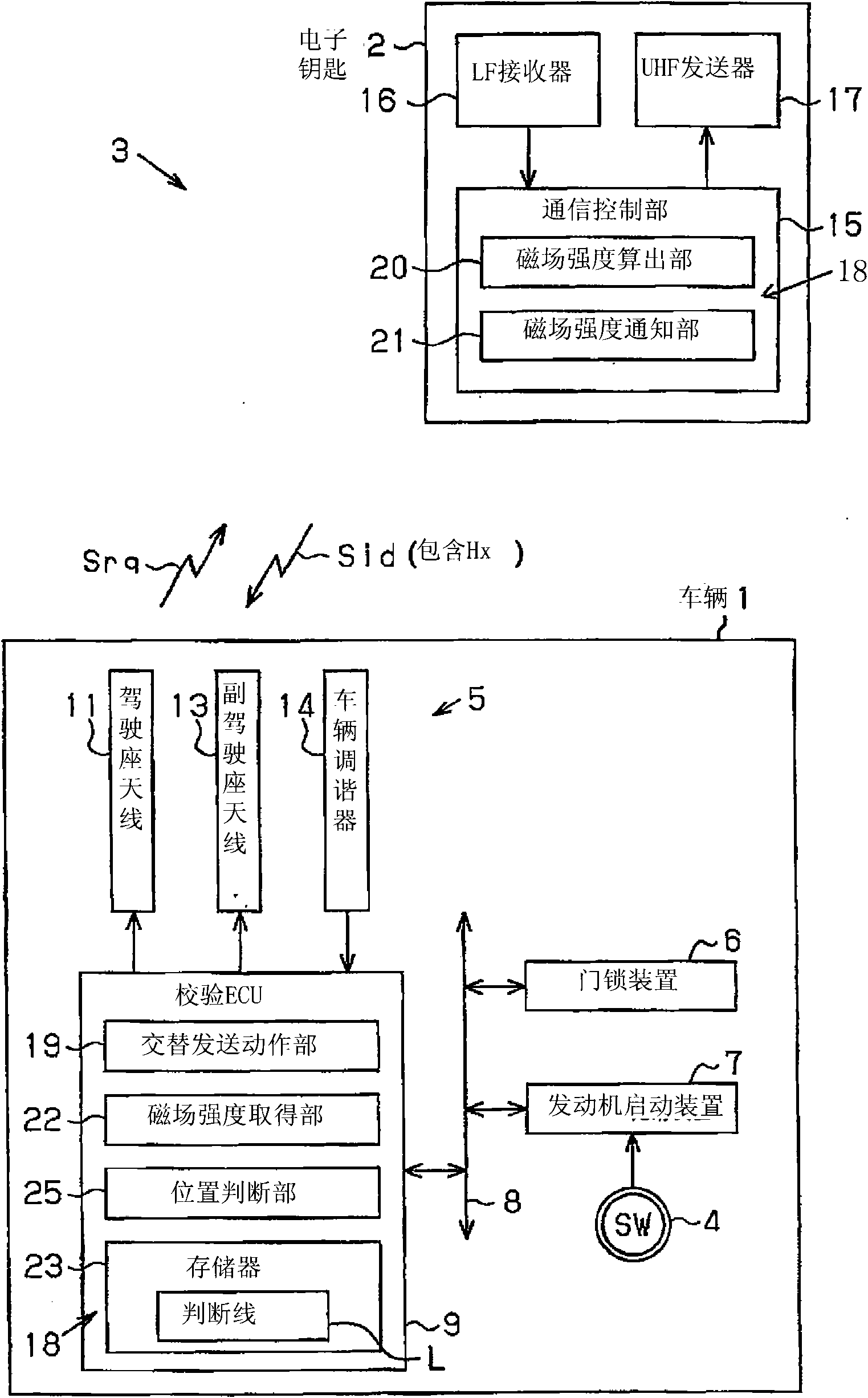
[0024] Below, refer to Figure 3 to Figure 9 A first embodiment of the communication terminal position determination device of the present invention will be described. In the first embodiment, the communication terminal position determination device is applied to an electronic key system.

[0025] Such as image 3 As shown, the vehicle 1 is provided with a keyless operating system 3 , which is a type of electronic key system that performs key verification in a wireless manner. In the keyless operation system 3 , ID (identification) verification is automatically performed on the electronic key 2 approaching the vehicle 1 . The keyless operating system 3 of this example is suitable for the smart entry system and the one-button engine start system. In the smart entry system, in a series of door opening and closing actions, it is possible to lock or unlock the door without performing actual key operation. In the one-button engine starting system, the engine can be started only...

no. 2 Embodiment approach

[0096] Next, refer to Figure 10 as well as Figure 11 A second embodiment of the communication terminal position determination device will be described. In the second embodiment, the communication terminal position determination device is applied to the tire air pressure monitoring system 50 . Hereinafter, the same symbols will be assigned to the same configurations as those of the first embodiment to omit detailed description, and only different parts will be described in detail.

[0097] Such as Figure 10 As shown, a tire pressure monitoring system 50 is mounted on the vehicle 1, and the tire pressure monitoring system 50 monitors the air pressure of each tire 51 through an electronic tube (tire sensor) 52 mounted on each tire 51 and capable of wireless communication. Once the tire pressure monitoring system 50 detects a tire whose tire pressure is lower than the threshold value, it notifies the driver of the tire information through, for example, the instrument panel i...


PUM


Abstract

A communication terminal position determination device is used for a wireless system which performs bidirectional communication between a communication host and a communication terminal. The wireless system comprises a first antenna and a second antenna, which alternately transmit an electric wave to the communication terminal under the control of the communication host. The communication terminal obtains the receiving strength of the first electric wave from the first antenna as a first receiving strength (Hd). Additionally, the communication terminal obtains the receiving strength of the second electric wave from the second antenna as a second receiving strength (Hp). The communication device receives the first receiving strength and the second receiving strength (Hd,Hp), and furthermore the communication host uses determination lines (L,La) formed on plane coordinates for displaying the position of a combined value (P) of the first receiving strength (Hd) and the second receiving strength (Hp) for determining a fact that the combined value (P) is larger or smaller than the determination lines (L;La;Lb) thereby determining the position of the communication terminal.

Description

technical field [0001] The invention relates to a communication terminal position judging device, which judges the position of a communication terminal (communicator). Background technique [0002] Conventionally, an electronic key system is widely used, which wirelessly transmits an ID code from an electronic key serving as a vehicle key to a vehicle and performs ID verification on the electronic key by the vehicle. As one type of the electronic key system, there is a smart key operating system (also called a keyless operating system). In this system, the vehicle transmits a request as an ID reply request, and ID verification of the electronic key is performed using the ID code sent back from the electronic key in response to the request. This smart key operating system is suitable for smart entry systems or push-button engine start systems. In the smart entry system, if the ID verification outside the car is established, the locking or unlocking of the car door is allowe...

Claims


Application Information

Patent Timeline
Patent Type & Authority Patents(China)
IPC IPC(8): B60R25/24H04Q9/00B60R25/00
Inventor 熊谷胜秀伏见晃
Owner KK TOKAI RIKA DENKI SEISAKUSHO
Learn More