
Design scheme for lamp tube body and lamp cap of light emitting diode (LED) fluorescent lamp

A technology of LED fluorescent lamps and design schemes, which is applied in the direction of lighting and heating equipment, semiconductor devices of light-emitting elements, light sources, etc., can solve problems such as time-consuming, reduce production progress, and increase labor costs, so as to reduce production costs, upgrade product quality, The effect of improving productivity

Inactive Publication Date: 2011-06-29
陆敬仁
View PDF0 Cites 0 Cited by
  • Summary
  • Abstract
  • Description
  • Claims
  • Application Information

AI Technical Summary

Problems solved by technology

[0006] In this way, there is an additional time-consuming process, which not only reduces the production schedule, increases labor costs, but also makes it difficult to control the consistency of product assembly quality
[0007] And this status quo is all due to the lack of a lamp body and lamp holder that are specially suitable for the characteristics of LED lighting.

Method used


Image

  • Design scheme for lamp tube body and lamp cap of light emitting diode (LED) fluorescent lamp
  • Design scheme for lamp tube body and lamp cap of light emitting diode (LED) fluorescent lamp
  • Design scheme for lamp tube body and lamp cap of light emitting diode (LED) fluorescent lamp

Examples


Embodiment Construction

[0026] Here are two embodiments to realize this patent:

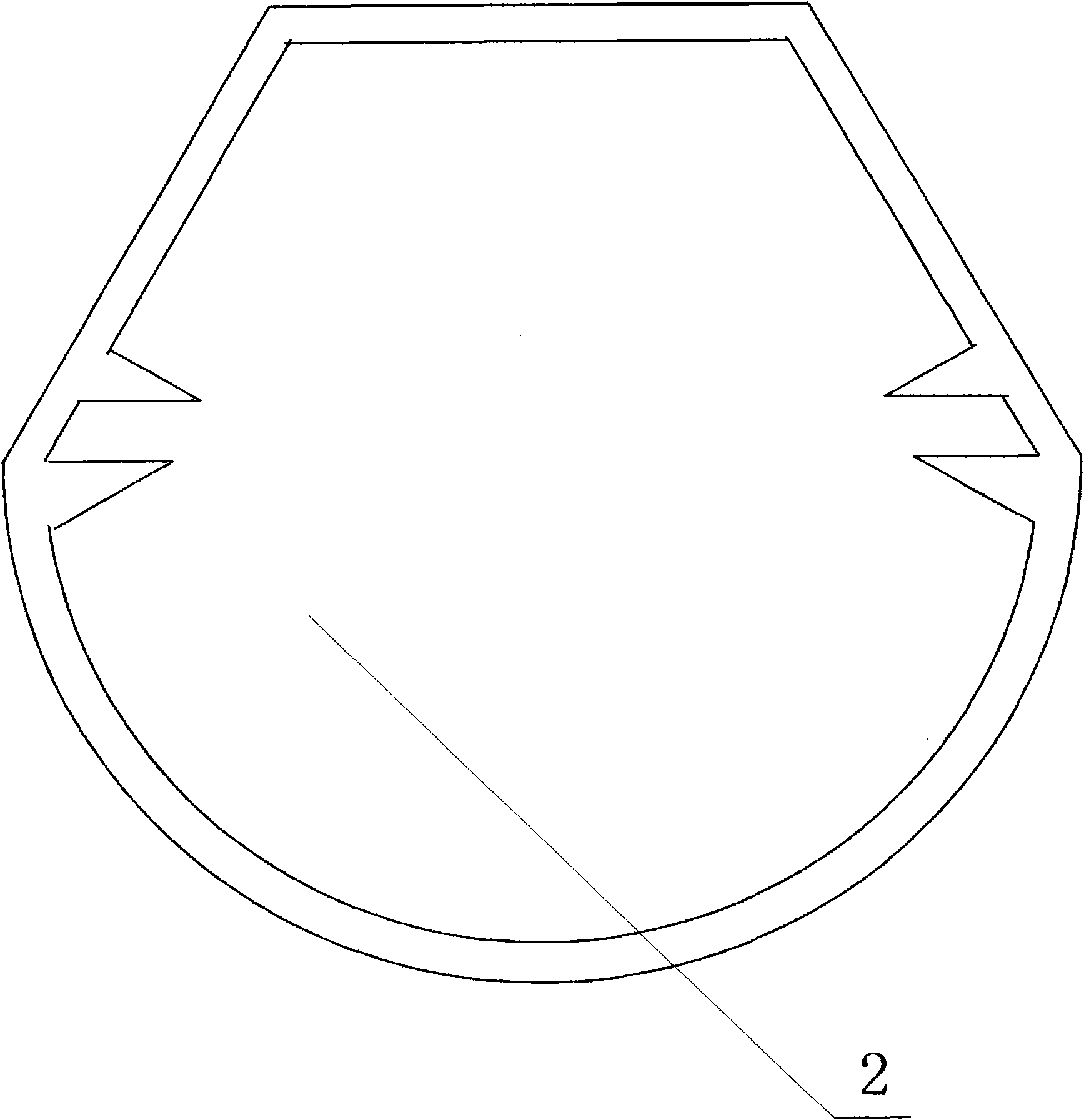
[0027] The first embodiment is to design an integrated special-shaped tube body (2) and a special-shaped lamp holder (6) matched with it, which are used as matching parts for the production of LED fluorescent lamps.

[0028] press figure 2 The cross-section of the integral special-shaped tube body (2) is shown to make a set of plastic die-casting molds, through which a certain length of integral special-shaped tube body (2) is die-casted with transparent PC plastic; Image 6 As shown, a set of stamping molds for metal parts is made, and the special-shaped lamp cap (6) is stamped out with thin aluminum skin through this set of molds, and the first embodiment is completed.

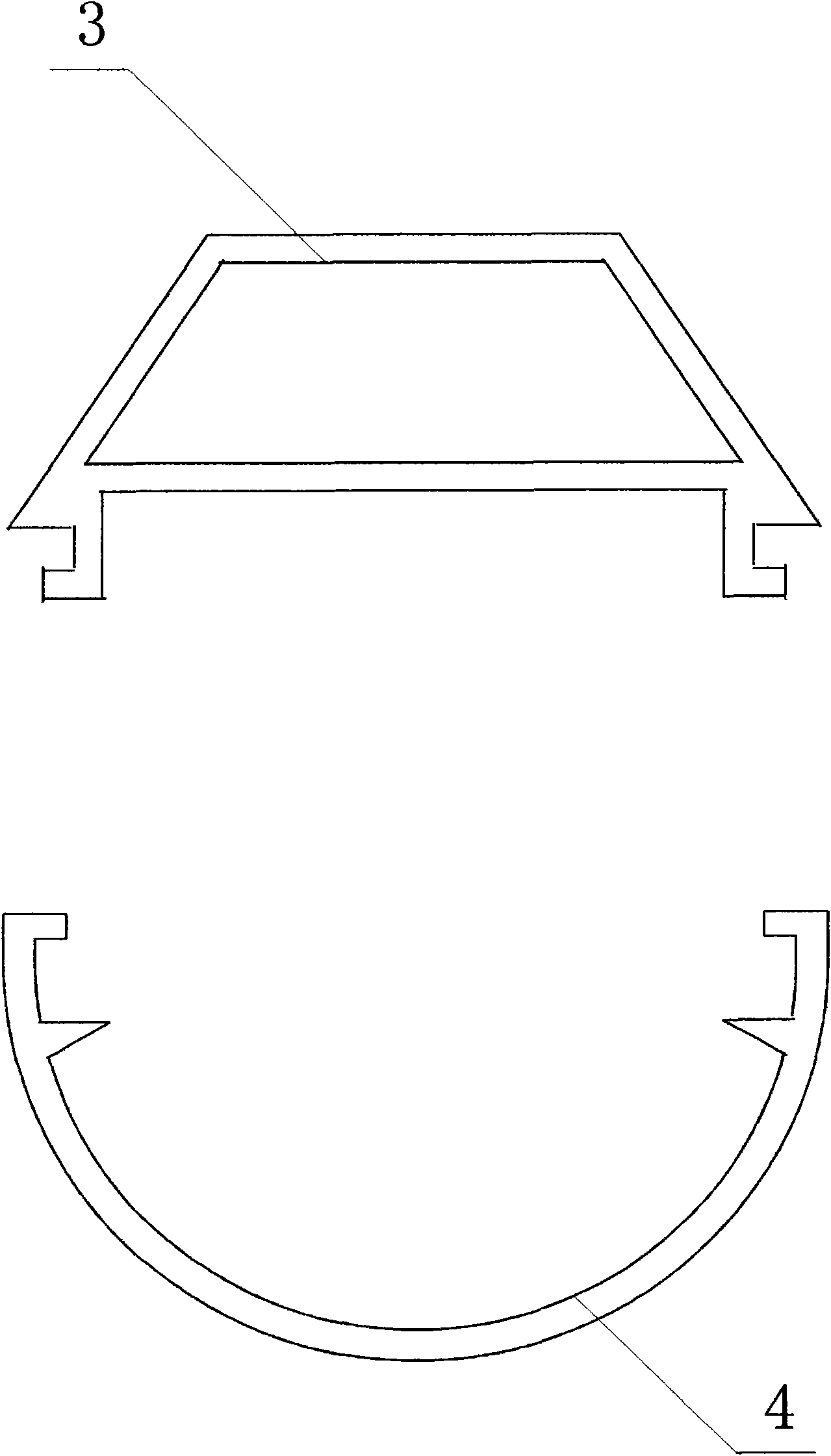
[0029] The second embodiment is to design a combined special-shaped tube body (5), the lamp holder still adopts the special-shaped lamp holder (6) as a supporting part in the production of LED fluorescent lamps. This set of accessories is used for LED fluo...


PUM


Abstract

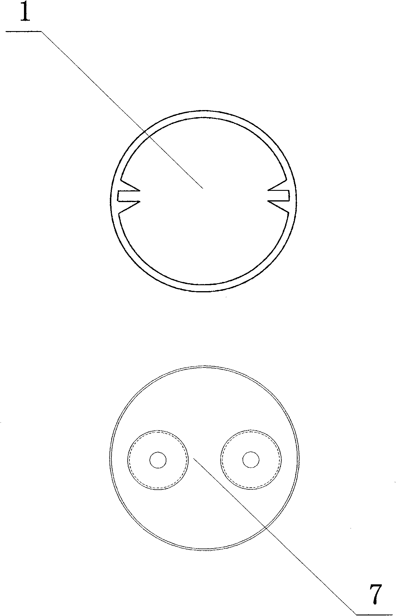
The invention discloses a design scheme for a lamp tube body and a lamp cap of a light emitting diode (LED) fluorescent lamp. A circular tube body and a circular lamp cap which are adopted by a common LED fluorescent lamp are abnormalized, so that the tube body is matched with the lamp cap in a unique direction. During production in which the tube body and the lamp cap provided by the design scheme are assembled to form the LED fluorescent lamp, used materials are not increased, but two troublesome alignment processes can be saved; and since the abnormally-shaped tube body is matched with the abnormally-shaped lamp cap in the unique direction and intentional alignment is not required, the design scheme has the three major advantages of: 1. improving production efficiency, 2. reducing production cost, and 3. upgrading product quality. The design scheme has immeasurable contribution to the innovation of a production flow of the LED fluorescent lamp.

Description

Technical field [0001] Mechanical component design. Background technique [0002] At present, the lighting source is undergoing a transitional period. LED lighting, with its many advantages, is very likely to become the dominant light source of the next generation. Many lamps in use now have corresponding LED products. [0003] Modeled on the fluorescent fluorescent lamps that are widely used today, various types of LED fluorescent lamps have naturally appeared. [0004] However, in the production process of LED fluorescent lamps, there is a prominent problem: the cooperation of the lamp cap and the tube body of the LED fluorescent lamp has one more process than the production of traditional fluorescent lamps: [0005] Traditional fluorescent lamps emit light in a 360° ring, so as long as the direction of the copper needles on the two lamp caps of the lamp is the same, the circular lamp tube does not need to be in the right direction when installing. In the current production process...

Claims


Application Information

Patent Timeline
IPC IPC(8): F21S2/00F21V3/02F21V3/04F21K9/20F21Y115/10
Inventor 陆敬仁
Owner 陆敬仁
Learn More