Cylindrical iron core, stationary induction apparatus and induction heat-generating roller device

A cylindrical iron core technology, applied in the field of circular iron cores, can solve the problems of enlarged outer diameter, inability to prevent eddy current, and limited usefulness, etc.

Active Publication Date: 2012-08-29
TOKUDEN CO LTD
View PDF6 Cites 0 Cited by
  • Summary
  • Abstract
  • Description
  • Claims
  • Application Information

AI Technical Summary

Problems solved by technology

However, if the width dimension is simply increased, there is a problem that the use will be limited due to the increase in the outer diameter
In addition, in order to reduce the outer diameter, it is also considered that the magnetic steel plate is arranged as inclined as possible in the radial direction, but in this way, the area of ​​the flat part exposed to the outside of the magnetic steel plate will become larger, and the generation of eddy current cannot be prevented. The problem

Method used


Image

  • Cylindrical iron core, stationary induction apparatus and induction heat-generating roller device
  • Cylindrical iron core, stationary induction apparatus and induction heat-generating roller device
  • Cylindrical iron core, stationary induction apparatus and induction heat-generating roller device

Examples


Embodiment Construction

[0053] (best form for carrying out the invention)

[0054]

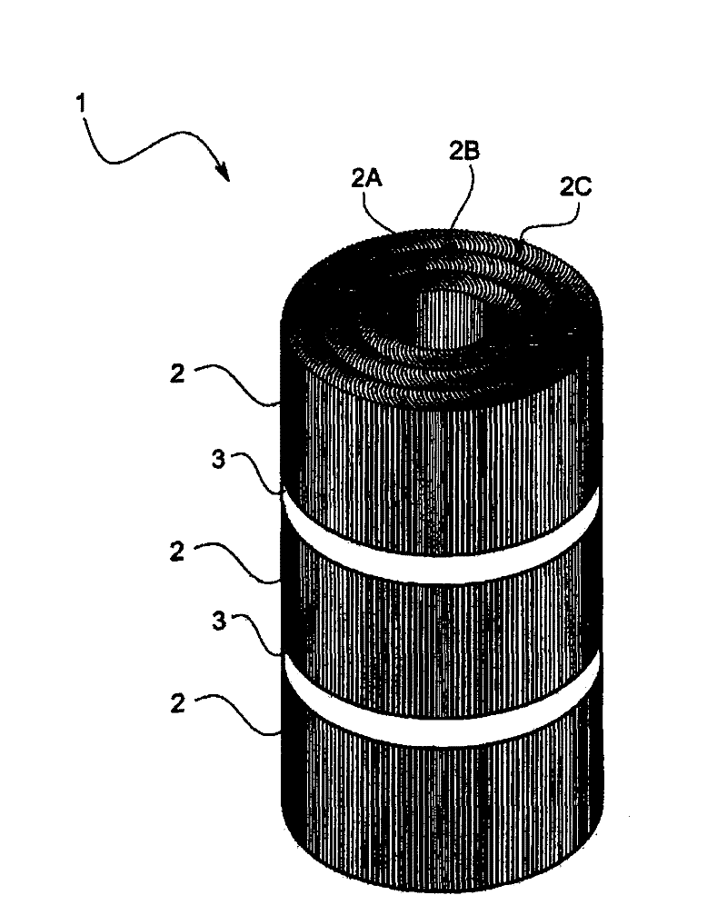
[0055] Next, an embodiment of the iron core 1 for static induction equipment according to the present invention will be described with reference to the drawings. Other, figure 1 It is a perspective view showing the outline of the structure of the static induction device core 1 of the present embodiment, figure 2 It is a top view of the iron core 1 of the static induction equipment.

[0056] The iron core 1 for static induction equipment related to this embodiment is, for example, a circular iron core used for a reactor or a transformer, such as figure 1 As shown, a plurality of core blocks 2X and a magnetic gap G provided between these core blocks 2X are included.

[0057] Core block 2X, such as figure 2 As shown, a plurality (three in this embodiment) of cylindrical core elements 2A, 2B, and 2C are stacked in a radial direction to form concentric circles. In the radial direction, adjacent cylindrical core e...


PUM


Abstract

Provided is a cylindrical iron core, in which a gap in the whole section of a stationary electromagnetic induction-type circular core of a transformer or a reactor can be reduced and iron loss due to leakage flux on the outer circumferential surface can be suppressed. The cylindrical iron core comprises a plurality of core blocks (2) formed by concentrically laminating cylindrical core elements (2A, 2B, 2C) which are formed by laminating a plurality of magnetic steel plates (21), each of which is provided with a curved portion (211) having a curved section in the width direction, while shifting from each other in the width direction.

Description

technical field [0001] The invention relates to a circular iron core (cylindrical iron core), which is used for static induction equipment such as a transformer or a reactor, and induction heating equipment such as an induction heating roller device. Background technique [0002] In static induction equipment such as transformers and reactors, the loss of the iron core as a magnetic circuit causes equipment efficiency reduction and heat generation, and the reduction becomes a major problem. In particular, the eddy current loss of the iron core caused by the leakage magnetic flux occupies a huge proportion, and this eddy current will cause the iron core to heat up, thereby reducing the efficiency of the equipment. Moreover, it becomes a factor which causes the efficiency of the induction coil wound on it to fall, and the insulation falls. In addition, it is known that the magnitude of the eddy current increases in proportion to the square of the width or the thickness of the...

Claims


Application Information

Patent Timeline
Patent Type & Authority Patents(China)
IPC IPC(8): H01F27/24H02K1/12H02K1/22H05B6/14
CPCH01F27/2455H02K1/12H01F3/14H05B6/14H01F27/263
Inventor 北野良夫外村徹冈本幸三弘田成之玉置幸男藤本泰广
Owner TOKUDEN CO LTD
Why Eureka
Try Eureka