Modular optical resonant chamber of high-power laser

A technology of high-power lasers and optical resonators, applied in the field of optical resonators, can solve the problems of unsatisfactory mechanical precision and fundamentally avoiding the stability of optical resonators, and achieve real-time high-precision monitoring and reliable and fast adjustment, high Effect of Precision Optical Axis Monitoring

Active Publication Date: 2012-11-07
NINGBO SIASUN ROBOT TECH CO LTD
View PDF0 Cites 0 Cited by
  • Summary
  • Abstract
  • Description
  • Claims
  • Application Information

AI Technical Summary

Problems solved by technology

At present, in engineering design, measures such as the use of high-performance materials and the design of special optical resonant cavity supports (referred to as optical bridges) are used to solve the impact of factors such as pressure, temperature, and vibration on optical resonant cavities, and it is expected to obtain absolute Stable optical cavity structure, but practice has proved that no matter how high the stability of the optical cavity is, the overall mechanical precision cannot meet the requirements of the optical system. This method can only reduce the influence of factors such as pressure, temperature, and vibration, and cannot fundamentally avoid it. The stability of the optical cavity during use, it can be said that there is no "absolutely" stable optical cavity structure and optical bridge support system in engineering

Method used


Image

  • Modular optical resonant chamber of high-power laser
  • Modular optical resonant chamber of high-power laser
  • Modular optical resonant chamber of high-power laser

Examples


Embodiment

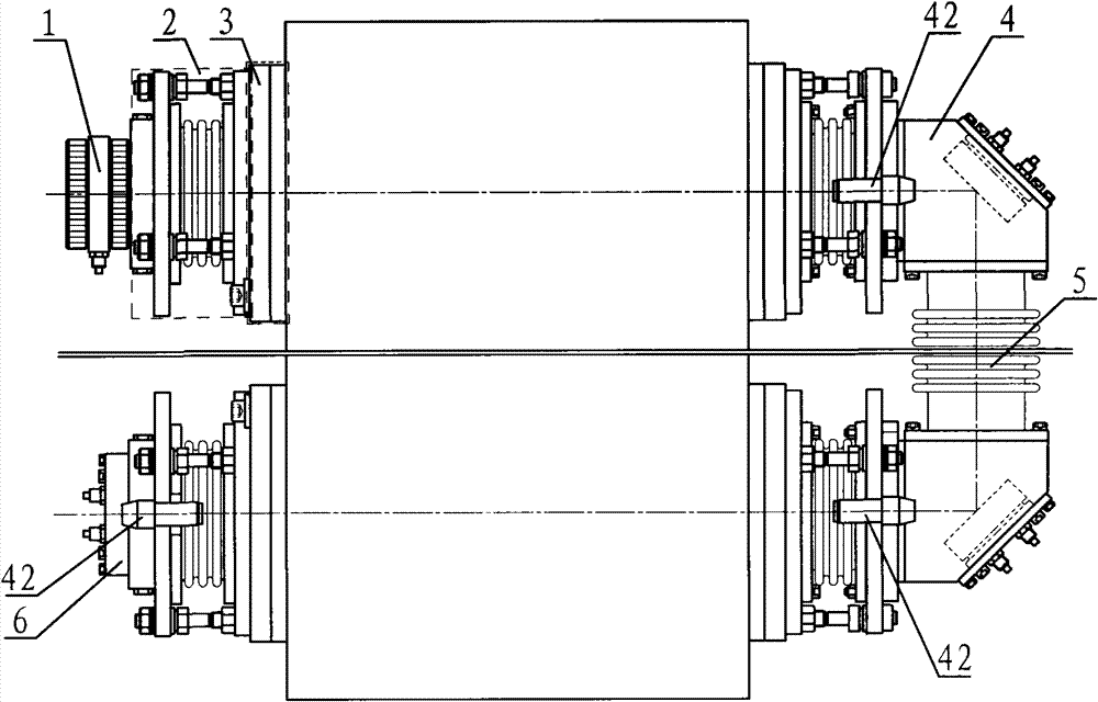
[0026] Embodiment: the present invention comprises a front window mirror module 1, a rear reflector module 6 and a middle folding mirror module 4, and the front window mirror module 1 and the rear reflector module 6 are respectively arranged on the laser through an angle adjustment module 2 and a position adjustment module 3 On one side of the box body 40, the middle folding mirror module 4 is divided into two groups, which are connected by a long bellows assembly 5, and are respectively arranged on the other side of the laser box body 40 through the angle adjustment module 2 and the position adjustment module 3, The rear mirror module 6 and the angle adjustment module 2 of the middle folding mirror module 4 are both provided with an optical axis monitoring module 42 .

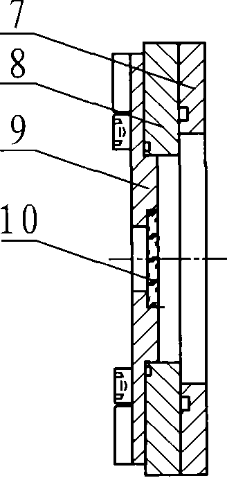
[0027] In this example, the position adjustment module is divided into four groups, and its structure is as follows figure 2 As shown, they all include a sealing flange 7 and an adjustable flange 8 connected ...


PUM


Abstract

The invention discloses a modular optical resonant chamber of a high-power laser, which belongs to the technical field of optical resonant chambers. The modular optical resonant chamber comprises a front window lens module, a rear reflector module and middle turning mirror modules, wherein the front window lens module and the rear reflector module are respectively arranged at one side of a laser box body through an angle adjusting module and a position adjusting module; two groups of middle turning mirrors are connected through a long bellows component and respectively arranged at the other side of the laser box body through an angle adjusting module and a position adjusting module; and the angle adjusting modules of the rear reflector module and the middle turning mirror modules are respectively provided with an optical axis monitoring module. An optical axis monitoring system is adopted for monitoring and compensating micro change of the optical resonant chamber, thus realizing a 'zero-error' stable optical chamber system; and the modular optical resonant chamber can realize high-precision monitoring and reliable and fast adjustment on the position and angle of chamber mirrors in real time. In the modular optical resonant chamber, an optical chamber supporting system is omitted, and a non-support modular structure system is realized.

Description

technical field [0001] The invention belongs to the technical field of optical resonant cavity, in particular to a high-power laser optical resonant cavity. Background technique [0002] In the field of high-power laser devices, obtaining a stable optical resonator is the key link to ensure stable laser output. At present, in engineering design, measures such as the use of high-performance materials and the design of special optical resonant cavity supports (referred to as optical bridges) are used to solve the impact of factors such as pressure, temperature, and vibration on optical resonant cavities, and it is expected to obtain absolute Stable optical cavity structure, but practice has proved that no matter how high the stability of the optical cavity is, the overall mechanical precision cannot meet the requirements of the optical system. This method can only reduce the influence of factors such as pressure, temperature, and vibration, and cannot fundamentally avoid it. ...

Claims


Application Information

Patent Timeline
Patent Type & Authority Patents(China)
IPC IPC(8): H01S3/081H01S3/139
Inventor 李雨邢飞范卫国贾吉庆
Owner NINGBO SIASUN ROBOT TECH CO LTD
Why Eureka
Try Eureka